Radiation Instrumentation and Measurement
- Film and Phosphors
- Gas-filled detectors
- Scintillation detectors
- Solid state detectors
- Neutron detectors
- Emerging and miscellaneous detectors
- In-vivo counting systems
- Quality control and quality assurance
- Measurement procedures
- Detection and Counting
- Applications in imaging, nuclear medicine, therapy and safety
- Basic Electricity
- General Electronics
Film and Phosphors
Opacity relative to exposure
Best resolution for relative dose distributions.
2-5% accuracy possible for absolute dosimetry.
Long term storage and dose record.
Facing beam for beam size, parallel to beam for PDD.
Radiographic film must be processed. Emulsion of Silver Bromide + gelatin layer + plastic base
Radiochromic film take time to develop on its own. Made of radio-sensitive chemicals that polymerize into optically opaque polymers upon irradiation (~24 hours)
Can be read on calibrated scanner (digitizer) by measuring optical density.
Advantages: High resolution, low energy dependence (MV range), low dose rate dependence, large area
Disadvantages: Readout is not immediate, batch variation (each needs calibration), orientation sensitive for digitization
Radiographic is sensitive to temperature, development process, dependent at low energies, not tissue equivalent, 3-5% accuracy
Radiochromic is accurate to 2-3%, also has tissue equivalency, energy independent to kV, 0.1 to 50 Gy useful range.
Optical density $OD = \text{log}\frac{I_0}{I_t} = -log_{10}(T) $ where $I_0$ is light collected without film, and $I_t$ is light transmitted through film and $T = I_t/I_0$ is the transmittance.
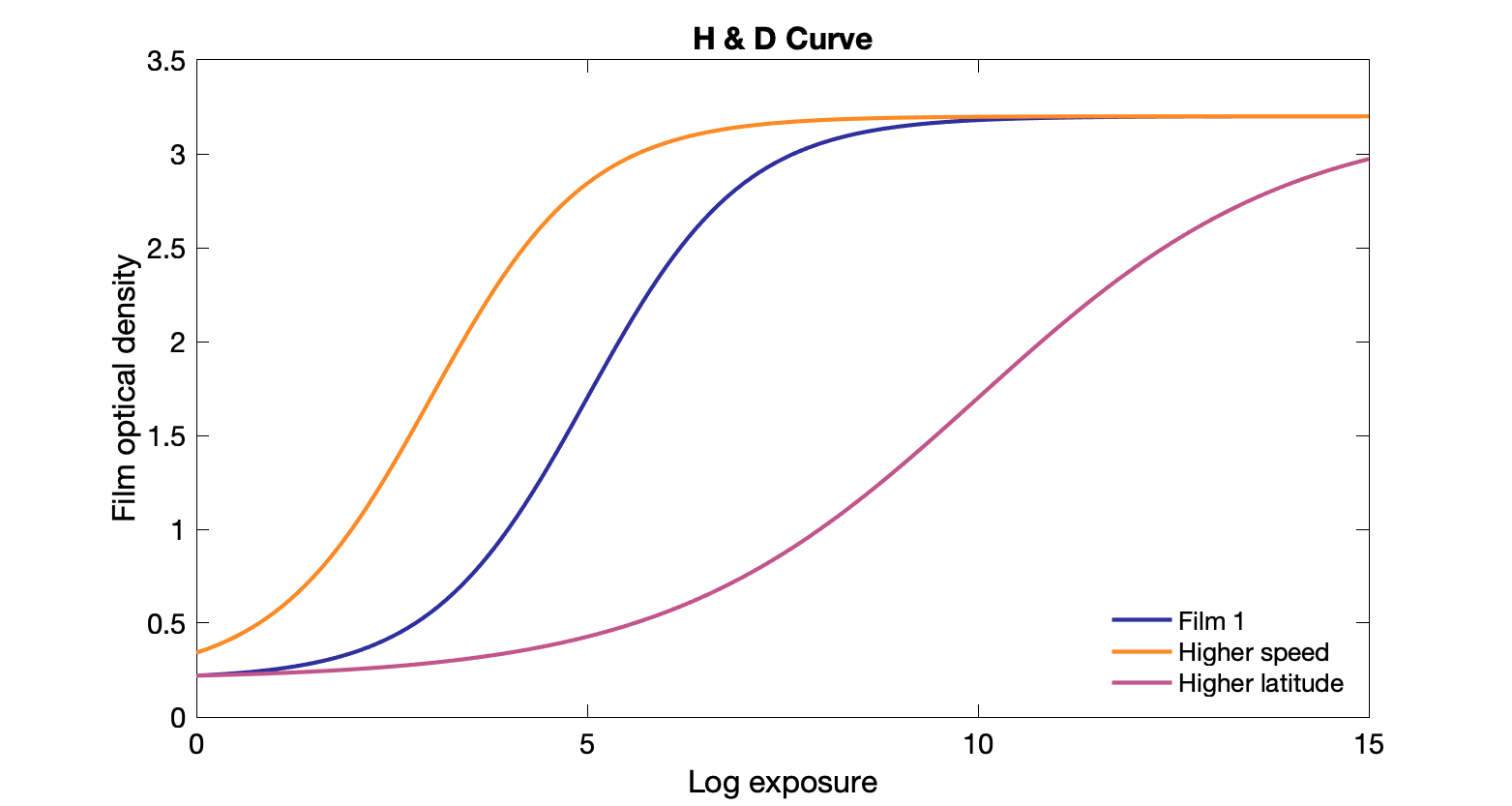
H&D curve: Plot of film density vs log of exposure
Gamma: slope of the linear region of the H&D curve. Steeper slope usually means higher contrast but smaller dynamic range
Dynamic range: the width of the linear region (useful range) on H&D curve, "latitude"
Higher dynamic range means lower contrast but can tolerate a larger range of exposures.
Speed: How much radiation is required to darken (sensitivity). Faster means less dose needed, but trade off is often resolution. Different speeds → lateral shift in H&D curve. Can have a more limited range of OD. Faster films are usually thicker. Can be useful for dose reduction.
Base+fog: natural attenuation + darkening from background radiation or light.
Typical resolution for film: 2.5 - 15 lp/mm
Intensifying screen: in from of film to increase detector efficiency (1% to ~30% interactions). Some extra blurring. Phosphors convert x-rays to visible light.
Film is often use to check leakage from x-ray housing.
Computed radiography: uses photostimulable phosphor (PSP) detector (barium fluorohalide doped with europium)
Energy of x-rays absorbed by phosphor electrons. Extra energy levels trapping electrons → latent image
Laser scan to release electrons from traps, collect light with PMT, convert to digital (ADC), and create image.
Flood with light to erase and reuse.
Wider dynamic range than film, no chemicals.
Gas Filled Detectors
Gas detectors consist of cathode, anode separated by a fill gas where ions are generated by ionizing radiation.
Exposure: ion pairs produced per unit mass $X = dQ/dm (C/kg)$
Special units of exposure: Roentgen (R): 1 R = 2.58 × 10⁻⁴ C/kg of air.
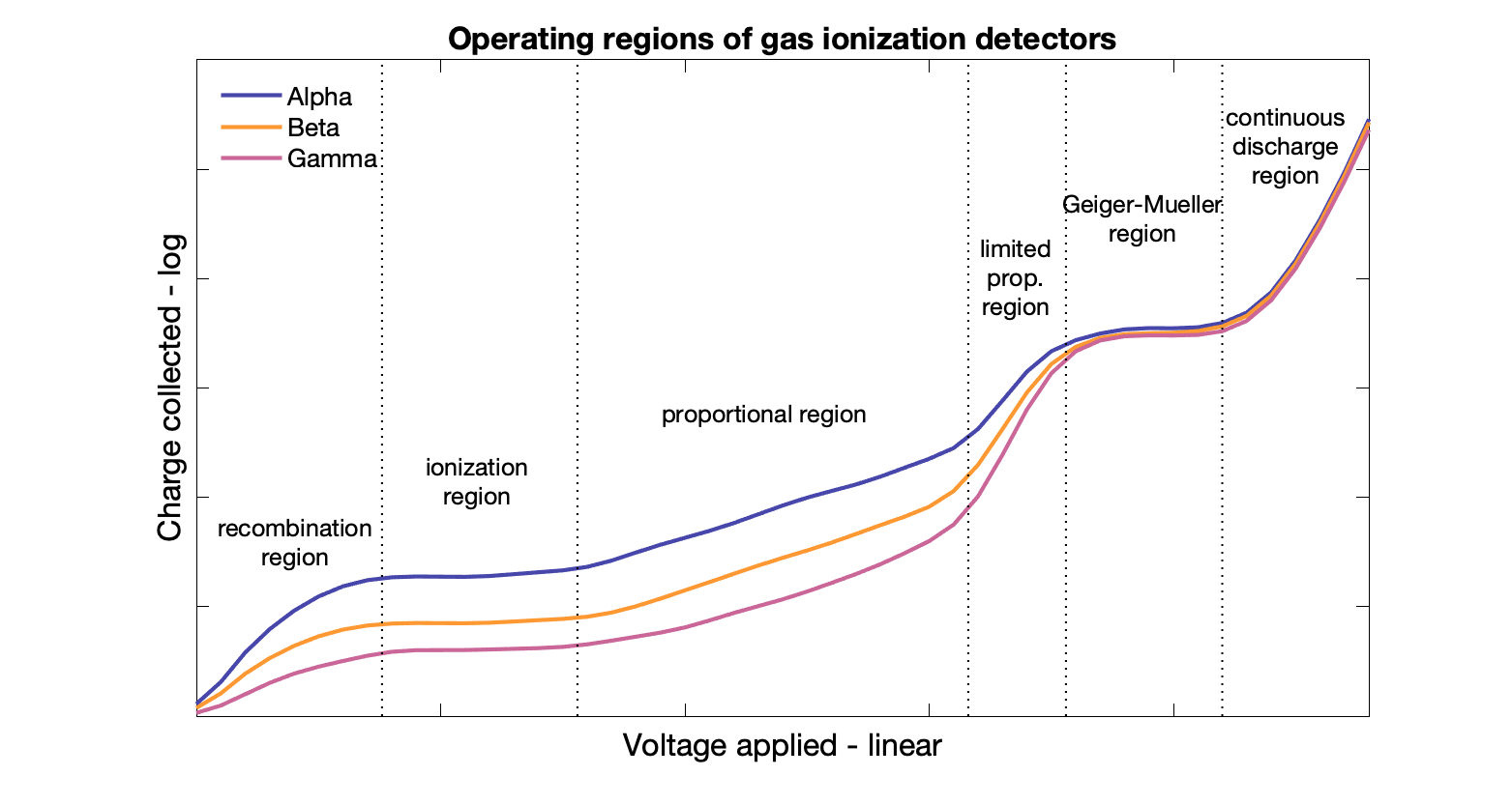
Recombination region: not useful, voltage is too low and some ion pairs that are created recombine before making it to the anode/cathode → signal is lower than it should be.
Ionization region
Low field, such that no gas multiplication occurs (ions that are generated by radiation do not create additional ions), but high enough to prevent recombination.
Ions drift to cathode while electrons drift to anode within the electric field generated by the applied voltage. The current generated by the charged particles is independent of voltage in this region. Signal is proportional to energy of incident radiation.
- Uniform response to photon irradiation - energy independent response
- Can measure high radiation rates
- Need electrometer to handle low output
- Operation and accuracy affected by moisture
Can be used as dose rate/survey meters, providing dose rate in mR/hr. Have lower limits of ~ 0.1 mR/hr. Energy independent response → good for isotopes that emit gammas of multiple energies.
Can be used to measure patient dose rate (nuclear medicine), and radiation package dose rate for shipping/receiving.
Ion chamber dosimetry
Ion chamber dosimetry for radiation therapy applications
Operated in ionization region (no secondary ionizations, relatively constant with voltage)
Bragg-Gray theory: $D_{med} / D_{gas} = (S/\rho)^m_{gas}$
Measure precisely with free air ionization chamber (standard used for calibration, e.g., at national standards labs).
$X = \Delta Q / (\rho A L)$ → essentially use charge collected divided by density * volume of air subject to ionization.
Farmer chambers + electrometers (op-amps) are commonly used for field measurements (calibrated by a standard lab).
Parallel plate chambers for surface dose measurements
Corrections for polarity (i.e., which electrode is held to ground), ion recombination, stem leakage, and temperature and pressure
$P_{T,P} = 101.33 / P * (273.2 + T) / (273.2 + 22)$ where T is in C and P is in kPa.
$P_{pol} = |\frac{(M^+ - M^-)}{(M^+ + M^-)}|$ where $M$s are the raw readings
$P_{ion} = \frac{1-(V_H/V_L)^n}{M^H/M^L - (V_H/V_L)^n}$ where $n$ = 1 for pulsed and 2 for continuous
$X = M\cdot N_{X}\cdot P_{T,P}\cdot P_{ST}\cdot P_{ion} \cdot p_{pol}$
$N_{X}$ is the calibration factor.
TG-51 Photons
Absorbed dose to water (Gy) is $D_w^Q = Mk_QN^{^{60}\text{Co}}_{D,w}$ where $M$ is the correct electrometer reading (see above), $k_Q$ is the quality conversion factor from 60Co beam to measured beam energies (depends on ion chamber type), and $N^{^{60}\text{Co}}_{D,w}$ is the calibration factor (Gy/C) in reference conditions.
TG-51 Electrons
Absorbed dose to water (Gy) is $D_w^Q = M k_{Q} N^{^{60}\text{Co}}_{D,w} = MP^Q_{gr}k_{R_{50}}' k_{ecal} N^{^{60}\text{Co}}_{D,w}$ where $M$ is the correct electrometer reading (see above), $P^Q_{gr}$ is a gradient correction factor, $k_{R_{50}}$ is the quality conversion factor, $k_{ecal}$ is the photon-electron conversion factor (depends on ion chamber type), and $N^{^{60}\text{Co}}_{D,w}$ is the calibration factor (Gy/C) in reference conditions.
IC Advantages: solid theory, low E dependence (50 kV to 50 MeV), low dose rate dependence (until saturation), accuracy < 1 %, real time readout.
IC Disadvantages: not arbitrarily small (volume averaging), needs ADCL calibration.
Calibration
Primary Standard Dosimetry Laboratory
• National standard: NIST or NRCC
Secondary Standards Dosimetry Laboratory
• Laboratory designated competent by PSDL to provide necessary traceable dosimetry standards to national standard
• ADCL: Accredited Dosimetry Calibration Laboratory (US version of SSDL), accredited by the AAPM (not NIST)
TG-21: Exposure / kerma factors
TG-51: Dose to water factors
Dose calibrators are used for assaying radiopharmaceutical activity in vials and syringes. Well-type ionization chamber (high geometric efficiency). Relates total ionization produced by sample to the total activity. Has large range from microcuries to curies. Able to give readout for various photon-emitting isotopes.
More details here
Pocket dosimeters collect charge over time and can be used to monitor radiation levels. Capacitor between electrode and case is charged to a reference voltage, such that Q = V × C. Radiation exposure results in charge collected on electrode, partially discharging capacitor. Voltage is then measured across capacitor and the change in V is then related to the change in charge Q. Needs device to charge and read. Not very efficient for photons (<1%), energy dependent (penetration of walls). T&P dependent if not sealed.
Proportional counters
Ion chamber in proportional range → gas multiplication (speeds high enough to eject secondary orbital electrons).
Charge collected is proportional to the applied voltage.
Each electron creates its own "Townsend avalanche" as it accelerates towards anode → additional signal.
Electrical pulse is proportional to energy imparted.
Preamp, linear amp, pulse-height analyzer (no electrometer).
Assumes constant $W/e$
Typically uses P10, a 90%/10% mixture of argon and methane.
Tissue equivalent proportional counter: microdosimetry (neutrons), laboratory counting. Absorbed dose to wall = absorbed dose to gas
Can measure dose, quality, LET.
Geiger-Muller counter
High voltage range, multiple avalanches from single ion pair. Both primary and secondary electrons are accelerated and avalanche. Tertiary electrons eject from anode and accelerated back.
Signal is independent of voltage and independent of incident radiation energy. Efficiency is higher at lower photon energies.
Displays count rate (and audible). Useful as survey meters for radiation monitoring. Dose rate (mR/hr) precise under certain assumptions only (response can vary with photon energy)
Cheap, robust, large signal for small radiation levels, and needs minimal processing.
No pulse discrimination (no radiation type distinction).
Dead time at high rates (high radiation levels) → not so useful.
Useful for surveying for contamination and finding lost radioactive seeds/markers.
Limited proportion region and continuous discharge - Regions that are not useful
Comparisons
Ionization: 300-600 V, response independent of V, low sensitivity, dose calibration
Proportional: 600-900 V, response proportional to V, medium sensitivity, research
Geiger counter: 900-1200 V, response independent of V, high sensitivity, survey meter
Scintillation counters
Emit flashes of light when ionizing radiation excites atoms in a crystal.
Organic or inorganic, solid or liquid
Fast response (< 10-8 seconds)
Properties: Atomic number (Z), light output, decay time, mechanical and optical properties.
Radiation excites electron, electron de-excites and emits photon.
Light must then be collected (reflected to detector) and measured - converted to electronic signal
Phosphorescence causes prolonged release of light (not ideal)
Light is typically measured photomultiplier tubes (PMT) or solid state silicon photomultipliers (SiPM) to convert visible light into an electrical signal.
Photons converted to electrons, then multiplied through series of dynodes.
High gain, low noise, fast, large collection area.
Photodiodes mostly used for imaging detector (fast response, directionally dependent, dark current, not radiation hard)
Organic scintillators: some crystals (stilbene, anthracene) plastic, liquid. Low Z (C and H). Hydrogen converts neutrons.
Response depends on LET. Fast decay but low conversion amount.
Inorganic: alkali metals: NaI (Tl), CsI (Tl), CsI (Na) - higher Z
Doping used to increase fluorescence.
Greater light output, longer emission times, output proportional to energy absorbed.
Efficient detection (high Z, high density), good for gamma rays.
Radiation hard up to several thousand Gy.
Imaging with scintillators:
PET: LYSO, BGO
SPECT: NaI(Tl)
CT: CdWO4
Flat planel: CsI(Tl)
Well counters typically use scintillation to measure small amounts of radioactivity.
Single NaI(Tl) crystal with hole in one end for high geometric efficiency.
Wipe tests samples, or in-vitro specimens (blood, urine) placed into well and measured in counts per minutes (cpm).
Scintillation probes often using a single CsI, NaI (or LYSO or BGO) crystal are used to estimate thyroid uptake, or small crystals intra-operatively for radio-guided surgery. Detect sentinel lymph nodes (99mTc sulfur colloid), locate 125I seeds in breast surgery, 18F-FDG biopsy.
Thyroid uptake typically uses NaI+PMT system close to organ. Quantify uptake in patients, and as bioassay to monitor worker exposure.
Details of scintillation
NaI(Tl) scintillators: One of the most widely used scintillators, used in gamma cameras, well counters, probes and other radiation detectors. Cheaply grown, but fragile and hygroscopic. Thallium (Tl) impurities are added to enhance scintillation (otherwise only scintillates at liquid nitrogen temps). Typically connected to a PMT to convert light into electronic signal.
- density = 3.67 g/cm3
- Zeff = 50 → good at absorbing photons in 50 - 250 keV range
- Decay time 230 ns (a bit slow)
- light yield 38 photons/keV (relatively efficient)
- emits 415 nm light (transparent to this wavelength, good match to PMT photocathode at ~ 400 nm)
Photoelectric effects dominate until ~ 250 keV, then Compton (lower detection efficiency) dominates until ~ 5 MeV when pair-production takes over.
More expensive than gas-filled detectors, but more efficient. Lower energy resolution than semi-conductors, but cheaper.(See comparison with other gamma camera scintillators.)
PET detectors: Higher energy photons (511 keV) require thicker or denser crystal. Usually bismuth germanate (BGO), lutetium oxyorthosilicate (LSO), or gadolinium orthosilicate (GSO). Desired qualities are high Z/high density to absorb the γ-rays, fast light signal for low dead time and time-of-flight applications, high light output for energy resolution.
See detailed comparison of PET scintillators on the nuclear medicine page.
Liquid scintillators: Useful for low-energy photons and betas (b/c low density and low Z material), esp. 3H and 14C, and for biologic specimens. Scintillator (solute) dissolved into solvent (e.g., DIN, PXE, toluene, xylene), radioactivity is added and pair of PMT tubes detected light photons. Solvent absorbs radiation, solute (e.g., bis-MSB or PPO) absorbs energy from solvent then emits light. Waveshifter solute can be added to help match scintillation light wavelength to that of the PMT. Additives can enhance performance and improve dissolution of samples (e.g., blood).
Low energy particles → fewer light photons produces → susceptible to background and electronic noise.
Container is usually polyethylene or low-potassium glass. Stored in darker container to avoid background phosphorescence from sunlight.
Thermal emission from PMT photocathode adds to background → keep at low (-10 C) temperature.
Pulse-height analysis used to discriminate between signal (larger) and noise. Superimposed noise still reduces energy resolution and linearity.
Coincidence circuit used to determine if light (emitted isotropically and reflected back from sides of container) reached both PMTs around same time (within ~ 0.03 μs). Noise is randomly distributed in time and unlikely to happen in coincidence. Random rate is $R_r = (2\tau)R_n^2$ where $2\tau$ is resolving time and $R_n$ is noise pulse rate per PMT. Higher PMT termal emission+phosphorescence (noise pulse rate) and worse timing resolution increase random rate.
MCA used to produce spectrum of energies of detected events.
Drawbacks
- ~Only 1/3 light output of NaI(Tl), and poor coupling to PMTs.
- Special sample prep required
- Sample is destroyed
- Quenching (reduced light output) - can result in similar samples resulting in different measurement results
- chemical: substances compete with primary fluor by absorbing energy, but don't scintillate (e.g. dissolved oxygen)
- color: substances that absorb primary or secondary emissions (blood, colored material, dirty container)
- dilution: too much sample vs scintillator solution
- beta-particle self absorption
- Reduced light output → noisier and energy underestimated (spectrum shifted left) → could miss energy window
- Can be adjusted using a known calibration sample, also dissolved into the solution:
sample (Bq) = [cps(sample) * standard(Bq)] / [cps(sample+standard) - cps(sample)] - Quenching can also be calibrated for each energy channel (can be noisy at low count rates)
- Can be adjusted using a known calibration sample, also dissolved into the solution:
Scintillator detector characteristics:
Detector efficiency ($\epsilon$): Conversion of incident γ-rays to visible light. Depends on material (density, Z), thickness, incident photon energy
Quantum efficiency: conversion of visible light to electrons in PMT. Varies by wavelength (usu. peak at 400 nm).
Peak to total (photofraction, $f_p$): fraction of γ-rays that produce output signal within the selected energy window, Depends on material and γ-ray energy (photoelectric absorption), and crystal size (bigger, more likely to capture scattered rays)
Photopeak efficiency ($\epsilon_p$): ratio of the number of full energy events to the total number of γ-ray photons incident on the detector. $\epsilon_p = \epsilon \times f_p$
Standard reference materials - Tritiated (3H) water calibrated by NIST or standard laboratory.
Energy calibration and linearity: NaI(Tl) is fairly linear, can use single calibration source for 0.2 - 2 MeV. Spectrometers and gamma cameras usually have multiple calibration settings for different energies.
Spectrum stripping: Comparison of spectrum against known standards starting with highest energy (subtracted - can get statistical errors, esp at low energies)
Dead time correction: Events can pile up if they are not separated by 2-3 x the dead time. For decay time of τ, max detection rate is 1/2τ. See considerations for paralyzable and nonparalyzable dead time. Scintillators are generally paralyzable.
| Detector | Signal (V) | Pulse Duration (μs) | Uses |
| NaI(Tl) + PMT | 0.1 - 1 | 0.23 | gamma camera, probes, well counter |
| LSO + PMT | 0.1 - 1 | 0.04 | PET |
| Liquid scintillator + PMT | 0.02 - 0.1 | 0.001 | Sample counting |
| LSO + APD | 0.00001 - 0.0001 | 0.04 | Small PET, PET/MR |
| Semiconductor | 0.0001 - 0.001 | 0.1 - 1 | Small PET |
| Gas proportional counter | 0.001 - 0.002 | 0.1 - 1 | Research |
| GM counter | 1 - 10 | 50 - 300 | Survey |
Solid state detectors
Semiconductors
Solid state version of gas ionization chambers. Examples: cadmium telluride (CT) or cadmium zinc telluride (CZT), Germanium lithium (GeLi), Silicon Lithium (SiLi).
Crystal lattice. Silicon. Doping to create donor electrons/holes. Typically pn-junction. P-type impurities → electron receptors. N-type impurities → electron donors.
Electrons transfer from valence to conduction band in response to incident radiation. Directly converts radiation to electrons (no intermediate light photons).
Band gap (electron energy) between conduction and valence bands is between insulator and conductor.
Voltage is applied to attract electrons and holes to electrodes, generates electric signal.
Forward bias reduce depletion zone, reverse bias increases depletion zone.
Electrometer to collect charge.
Generally much higher efficiency that gas-filled detectors: higher density (by several orders of magnitude), only 3-5 eV needed for ion pair vs 34 eV in air. Larger electrical signal, proportional to amount of radiation energy absorbed (used for energy-selective counting).
Better spatial and energy resolution than scintillators. More compact (also means less sensitive)
Can have thermally-induced current (Si and esp Ge), creating background noise. Need a cooling system. Also need to avoid impurities (electron traps, reduce signal). Either high purity (HPGe) or add lithium impurities to donate electrons: Si(Li) and Ge(Li), but only make small (< 1cm and <5 cm) crystals. Store and operate at low temperature.
Cadmium telluride (CT) or cadmium zinc telluride (CZT) operate at room temperature w/o much noise, have higher Z, so thinner detectors have good stopping efficiency for γ-rays. Costly, so used in smaller detectors (e.g. microPET).
Diode
Measure current or charge. Real time readout.
Uses: small fields, electron PPD, In-vivo, > 5cGy doses
Dependencies: temperature, dose rate, energy, field size, angle (beam direction), changes with accumulated dose
Details: Junction of P-type and N-type semiconductors with depletion zone. Buildup cap to measure surface dose. Leads for readout. Electrometer to measure induced current. Typically no bias (little leakage current, no cooling needed).
Advantages: small, good for small fields and large gradients. Stopping power ratio constant over RT energies. Portable and robust.
Luminescent dosimeters, often used in personnel badges and in-vivo dosimetry during therapy.
Thermoluminescence: convert radiation energy to different energy, uses phosphorescence
Heat to release electrons from traps (created by impurities), PMT to measure light. Traps will leak over time.
CaF2 (Mn) for x-ray exposure only
LiF (Mg, Ti) for x-ray and neutrons
Glow curve: TL intensity vs temperature. Area under highest peak to calculated dose.
Small, onsite readings, reusable, dose response linear to 10 Gy.
Lack uniformity (batch calibration), readout removes signal, storage unstable, fading with use
Optically stimulated luminescence: use laser light to release electrons from traps
Light intensity linear to dose
Al2O3 (C), almost tissue equivalent
Can be kept and read out multiple times (only read about 0.05% of traps)
Reuse after flooding with light (anneal)
Individually calibrated.
Dose response linear only to 3 Gy. Sensitivity drops ~4% for every 10 Gy cumulative.
Neutron detectors
Tissue equivalent prop counter: microdosimetry. Absorbed dose to wall = absorbed dose to gas
Can measure dose, quality, LET, kerma factors, Boron neutron capture doses.
Reactions of interest
- $^{10}\text{B}(n,\alpha)^7 \text{Li}$, Q = 2.3 or 2.7 MeV
- $^{6}\text{Li}(n,\alpha)^3 \text{H}$, Q = 4.8 MeV
- $^{3}\text{He}(n,p)^3 \text{H}$, Q = 0.764 MeV
- $^{235}\text{U} \text{Fission}$, Q = 200 MeV
High Q and high stopping power make good discrimination with photons.
Detectors
- BF3 proportional counter
- Boron-lined proportional counter
- Boron and lithium-loaded scintillators
- 3He proportional counter
- Fission (ionization) chambers (typically used for reactor instrumentation due licensing issues)
Foil activation: thin to avoid perturbation, neutrons activate (neutron capture), emitted γ-rays are counted by a high purity germanium (HPGe) detector or NaI detector.
# of γ-rays proportional to neutron fluence × cross section
Track-etch: passage of charged particles create trail of damage. Density of tracks proportional to charge particle fluence and thus neutron fluence. (Bubble detectors)
Bonner spheres: varying diameter polyethylene spheres with BF3 detector or Au foils. Different diameters changes moderation. Unfold response to obtain spectrum.
Emerging and miscellaneous detectors
Chemical dosimeters
Chemical dosimeters rely on metal ions in aqueous solution being transferred to different oxidation state
Fricke dosimeter: Fe2+ + OH + radiation → Fe3+ + OH-
- Iron transition detected using spectrophotometer
- Tissue equivalent, can be any shape and solidified as a gel.
- Use MRI to get 3D dose distribution in gel. Blurring from diffusion
Polymer gel: Radiation induced polymerization. Optical properties change. Gel matrix, won't migrate.
3D dose distribution, but expensive and difficult. Not great clinically.
Polymerization shortens T2 (less molecular mobility)
Opacity changes → use optical CT for readout
Calorimetry
Measure energy deposited by temperature change. Typically done in standards lab.
Water to graphite. Difficult: 1 Gy results in temperature change of 0.00024 K.
Diamond
Carbon → tissue like mass stopping power.
Resistance inversely proportional to dose rate.
Can be very small. Radiation hard. Little directional dependence.
Use for penumbra measurements
In-vivo counting systems
Used for counting γ-radiation (low energy x- & γ-rays, α and β- typically won't penetrate tissue far enough.
- NaI(Tl) Probe Systems: Single Na(Tl) detector mounted on stand and connected to an SCA for energy selection. Can be pointed at area of interest with cylindrical or conical collimation. Most used for thyroid tests and treatments.
Calibration must account for attenuation and scatter. Narrow energy window around photopeak can help reduce scatter counts. - Mini probes: Intra-operative. Need high efficiency (easy to find active tissue), lightweight, not hazardous.
- Guide biopsy of sentinel lymph nodes: Inject 99mTc-labeled colloid that gets trapped in the first lymph node that drains the tumor.
- Injecting tumor-seeking radiopharmaceutical, wait for accumulation, then surgery. Probe is used to locate cancerous tissue.
- Crystal is usually CsI(Tl)coupled to Si photodiode detecting 111In, 131I, or 18F.
- Direct conversion semiconductors like CZT or CdTe are used for 99mTc (lower energy)
- Whole body counters - measure total radioactivity in body w/o localization. Used to study retention and clearance of longer lived isotopes.
- Typically use large NaI(Tl) detectors (thicker than imaging detectors).
- Needs good efficiency because of small amounts used (< 50 kBq).
- Can be used to monitor accidental ingestion of radioactivity.
Quality control and quality assurance
TG-51 (calibration protocol for photon and electron beams)
Absorbed dose to water $D^Q_w = M k_Q N^{^{60}Co}_{D,w}$, where $M$ is measured reading from electrometer, $k_Q$ is the quality conversion factor to convert to a given beam energy spectrum (quality) from the Co-60 standard used in calibration. $N^{^{60}Co}_{D,w}$ is the calibration factor in a Co-60 beam.
Dose measurements for photons are typically done at a depth in water of 10 cm with a 10 × 10-cm field size and SSD of 100 cm. The quality of a beam can be described by this quantity, "%dd(10)".
Dose measurements for electrons are done with ≥10 × 10-cm field size and 100 cm SSD. Depth is relative to the depth in water where the percent depth dose is 50%: $R_{50}$.
Electrons measurement depth: $d_{ref} = 0.6 R_{50} - 0.1 \text{cm}$
$R_{50} = 1.029 I_{50} - 0.06$ where $I_{50}$ is point of 50% ionization
Exposure rate
Each radioactive source has a specific exposure rate constant, typically given in R m2/h/Ci (Roentgens per hour at 1 meter for a source activity of 1 Ci)
Depends on number of photons and photon energy spectrum
Measurements of absorbed dose
Calorimetry - heat generated (small), measured with thermistors
Chemical - Ferrous Sulfate (Fricke) Dosimeter (Fe2+ oxidized by radiation to Fe3+)
Solid state - integrating (thermoluminescent crystals, film), electrical conductivity (semi-conductors)
Commonly used: Thermoluminescent dosimeters (TLD), Diodes (in-vivo monitoring instant response, but energy dependent and damagable), radiochromic film (tissue equivalent, high res, large dynamic range, low energy sensitivity, no chemical processing)
Film - optical density $OD = \text{log}\frac{I_0}{I_t}$ where $I_0$ is light collected without film, and $I_t$ is light transmitted through film.
H-D curve
Better for electron dosimetry than photons (silver, so not tissue equivalent). Good for checking field sizes and placements, flatness and symmetry.
Energy dependent - increased sensitivity to low energy photons
Measurement procedures
Dead time considerations
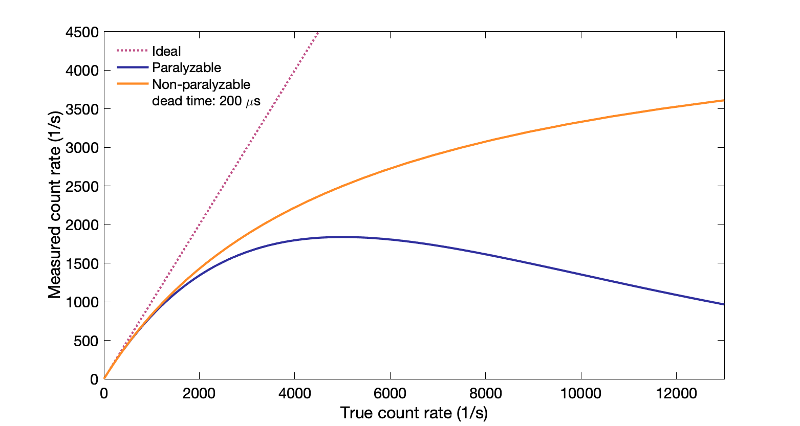
Dead time: time after event when system is not able to record another event.
Non-paralyzable count rate: $T = \dfrac{M}{(1 - M \, d)}$ where $T$ is true count rate, $M$ is measured count rate, and $d$ is dead time
Events during the dead time interval are missed.
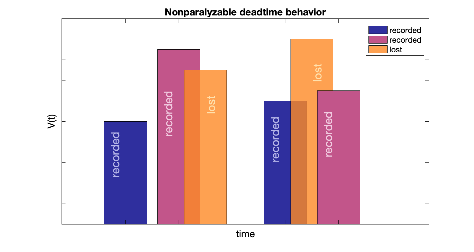
Maximum measured count rate (saturation rate) is inverse of dead time: $1/d$
Paralyzable count rate: $M = T\,e^{-T d}$, where $T$ is the true count rate, $d$ is the dead time, and $M$ is the measured count rate
Events happening during dead time are missed, and restart the dead time "clock" (events occurring during the lost event interval are also lost). With enough counts, nothing is recorded.
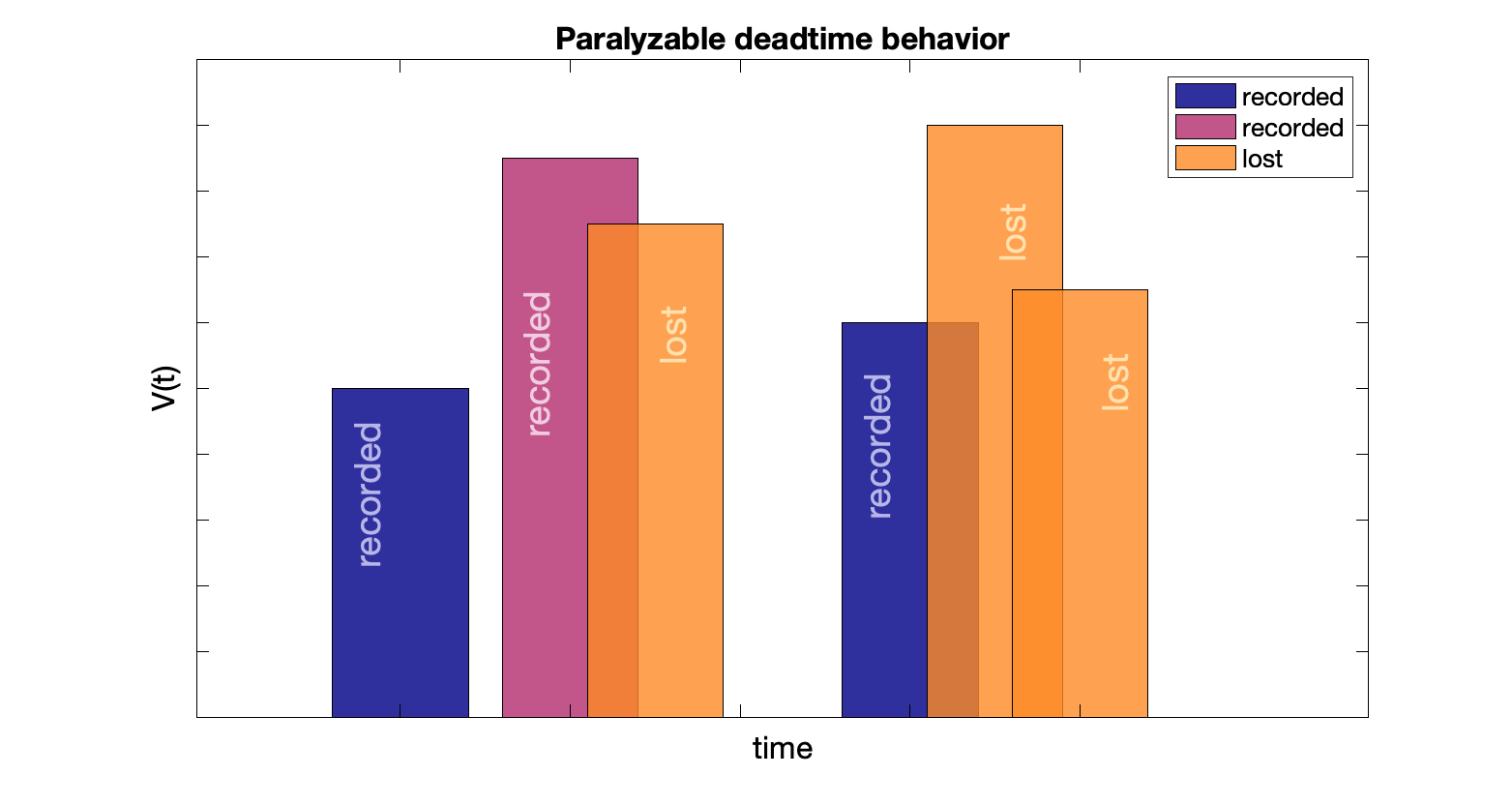
Maximum measured count rate, $1/(d \, e)$, is when the true count rate is at the inverse of dead time: $1/d$
Non-paralyzable examples: Geiger counter (with quenching gas), scaler and PHAs
Paralyzable: well counter, gamma cameras, PET cameras
Dead time measurement with radioactivity: two sources with expected 10-20% dead time loss. Determine counting rate for each alone and both together. (Note: take measurements at equal time intervals, or decay corrections are needed if radionuclide is short-lived.)
Can also plot measured count rates vs known activity amounts.
$\tau_n \approx (R_1 + R_2 - R_{12}) / (R^2_{12} - R^2_1 - R^2_2)$
$\tau_p \approx [2R_{12} / (R_1 + R_2)^2]\text{ln}[(R_1 + R_2) / R_{12}]$
Minimum detectable activity
On the opposite side, for low count rates, there is a minimum detectable activity (MDA) to get a statistically significant measurement. The MDA is that which has a count rate of at least three standard deviations above the background count rate: $\text{MDA} = 3\sigma_R = 3 \sqrt{R_B/t}$
Detection and Counting
Detector operating modes
Three primary modes of operation
Pulse mode
"Photon counting": Individual photon events are counted (detected and processed in real time).
Can provide energy discrimination.
Is susceptible to dead time, wherein interactions are lost. This means pulse mode is not useful for high count rates if the time between interactions is shorter than the dead time.
Examples: well-counter, scintillation camera
Current mode
Energy / charge-integrating: Individual events are not distinguishable, but detector outputs a current proportional to the energy deposited. It integrates charge collected from many photon interactions per unit time. Measures average rate of energy deposition.
Better for high count rate situations than pulse mode, but cannot distinguish events or their energies.
Example: survey meter, dose calibrator
Absorbed dose mode
Integral/cumulative dose: Collects and stores dose over an interval of time. Measures cumulative energy deposition. Can be real time or stored and read out later (e.g. TLD/OSLD). Cannot distinguish events or their energies.
Examples: Personnel dosimeter, ion chamber
|
|
Pulse mode |
Current mode |
Absorbed dose |
|
Energy discrimination |
Yes |
No |
No |
|
Individual events |
Yes |
No |
No |
|
Dead time |
Yes |
No |
No |
|
Dose determined |
No |
No |
Yes |
|
Examples |
Well-counter, scintillation camera |
Survey meter, dose calibrator |
Dosimeter, ion chamber |
Energy resolution
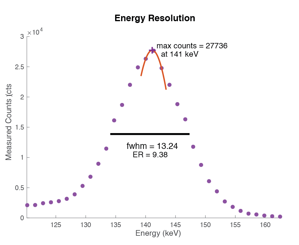
Ability to distinguish particle energy. Measured by amount of spread around expected energy peak. Typically given as FWHM of energy spectrum divided by the photopeak energy.
Important in spectroscopy and in nuclear medicine imaging.
Detection efficiency
number of useful photons detected / number of photons emitted
- Geometric efficiency (g): depends on detector size, shape, distance, location
- Intrinsic efficiency (É›): depends on detector thickness, type, energy of photons
- Measure of the ability to absorb incident radiation and convert to a usable signal
- Energy selective counting efficiency (f): fraction of output from detector that are recorded using pulse-heigh-analyzer
- Absorption and scatter (F): depends on source, medium and detector materials
Total detection efficiency $D = g × ε × f × F$
Geometric efficiency
$g$ is the geometric efficiency and is the number of photons reaching the detector / number of photons emitted
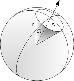 Need to consider the fraction of a spherical surface area extending from the source that the detector covers:
Surface area of sphere given by $A = 4 \pi r^2$
Detector of area $A_0$ at distance of $r_0$ from a source will cover $g = \frac{A_0}{4\pi r_0^2}$ of the sphere surface.
Geometric efficiency for a detector close to a point source depends on the angle subtended "around" the source.
$g_p \approx \frac{1}{2}(1-cos(\theta))$
Detector surrounding a source has 180° angle → $g_p = 1.0$
Detector flush to a source has 90° angle → $g_p = 0.5$
Detector partly surrounding a source has 90° < angle < 180° → $g_p = $ between 0.5 and 1.0, depending on depth and configuration (e.g. a well counter).
Intrinsic efficiency
$\epsilon$ is the intrinsic efficiency and is the number of photons interacted with the detector / number of photons reaching the detector.
Depends on radiation type and energy, and material (Z and ρ) and thickness, $x$, of detector.
$\epsilon = 1 - e^{-\mu(E) x}$ where $\mu(E)$ is the energy dependent linear attenuation coefficient for the radiation type and detector material.
Intrinsic efficiency increases with increasing thickness and μ (depends on photon energy, Zeff, and ρ).
Intrinsic efficiency decreases with increasing energy (μ decreases, less likely to interact).
Energy selective fraction
$f$ is the number of photons within a chosen energy window / number of photons interacted with the detector
If gamma rays Compton scatter, they may have lower energy and won't be included in the energy window of the pulse-height-analyzer (for detectors that employ this constraint).
The photofraction (f) depends on the detector material, the photon energy, and the crystal size.
Absorption and scatter factor
An absorbing and scattering medium around a source will alter the number and energy of photons reaching the detector.
Absorption will decrease counts, depending on attenuation of material and energy of photons
Scatter can decrease or increase counts, depending on distribution of sources and material and location of the detector.
$F$ depends on photon energy, depth of source in medium, and the chosen energy window.
Detection efficiency is the number of useful photons detected / number of photons emitted: $D = g × ε × f × F$
Activity counting
Measure counts per minute (cpm), divide by decays per minute (dpm), divide by yield (# gammas/decay).
$\epsilon = \frac{cpm}{dpm \cdot yield} \times 100 $
Detectors such as well counters can be calibrated based on known samples of long half-life isotopes, usually Cs-137, Ba-133 or Co-57.
Propagation of errors in count rates:
$N$ counts over time $t$ gives a count rate $R = N/t$.
Generally assume that $t$ has small enough uncertainty to be considered a constant.
Uncertainty in counting rate: $\sigma_R = \dfrac{\sigma_x}{t} = \dfrac{\sqrt{N}}{t} = \sqrt{\dfrac{R}{t}}$
→ What matters most for uncertainty (random errors) is the total number of counts collected.
Example:
40,000 counts vs 40,000 cps measured in 100 seconds.
Uncertainty in counting 40,000 counts is $\sigma_N = \sqrt{N} = \sqrt{40000} = 200$ counts → relative standard deviation is 0.5%.
Uncertainty in 40,000 cps counted for 100 s is $\sigma_R = \sqrt{R/t} = \sqrt{40000/100} = 20$ cps → relative standard deviation is 0.05% (effectively collected 4,000,000 counts)
The important numbers in determining uncertainty are the total counts collected and number of background counts relative to gross counts .
Measurement with background is the gross counts minus the background counts: $N_s = N_g - N_b$ and $\sigma_s = \sqrt{N_g + N_b}$ and fractional standard deviation is $\sigma_F(N_s) = \dfrac{\sqrt{N_g+N_b}}{N_g - N_b}$
Minimum net counts that can be detected with 99.7% confidence (3σ): $N_g - N_b > 3\sigma(N_g - N_b) = 3 \sqrt{N_g + N_b}$
Basic Electricity
Voltage: Electromotive force. Difference in electric potential between two points. SI unit: volt
Current: Rate of flow of electric charge past a point. E.g., electrons in a wire. SI unit: ampere
Resistance and Impedance: Opposition that a circuit has to a current when voltage is applied. Impedance, $Z$, is the AC-equivalent to DC resistance. $R = V/I$ and $ Z = V/I$. SI unit: ohm
Ohm's law: Current, $I$, through a conductor is proportional to the voltage, $V$, across the two points. Constant of proportionality is the resistance, $R$.
Voltage equals current times resistance: $V = IR$
Capacitance: Proportionality between voltage and charge (the ability to store electric charge), $C = Q/V$. SI unit: farad = coulomb / volt
Inductance: Tendency of a conductor to oppose a change in the current flowing through it. Inductance, $L$, is the ratio of induced voltage to rate of change of current causing it. $L = \Phi(i) / i$ where $\Phi$ is the magnetic flux. For an AC current, the peak voltage equals frequency times inductance times peak current: $V_p = \omega L I_p$. SI unit: henry = weber / ampere
General Electronics
Detectors of radiation are generally either direct (gas and semiconductor), which generate a current directly, or indirect (scintillators) which convert high energy photons into light, which is then converted into a charge and multiplied with a PMT or SiPM. Those electric signals are processed with various electronics to produce useful outputs depending on use case.
Electronic devices have an internal resistance and capacitance, and thus an output impedance. It can be used to model a sources response to current.
Preamplifier: amplifies low signals (radiation detectors range from ~0.01 V for direct semiconductor detector to ~10 V for a GM counter).
Adjusts and shapes the voltage of the pulse.
Matches impedance between detector and rest of the electronics. Matching impedance allows for maximum power transfer.
Amplifier: additional amplification, usually 1-1000x, with output pulses up to 10V.
Long signals (~500 μsec) can be reshaped into shorter signals and avoid pulse-pileup and incorrect amplitudes. RC shaping (differentiation and integration in combination).
Unipolar pulse (differentiation plus integration) for energy resolution and good signal to noise.
Bipolar pulse (double differentiation plus integration) for high count rate. Shorter rise time and positive portion, longer total duration (voltage goes negative).
Pulse Height Analyzer (PHA): Selects for counting only pulses that fall within predetermined voltage intervals (corresponding to the incident photon energy). Interval can be set by upper and lower levels, or by a peak and a percentage width.
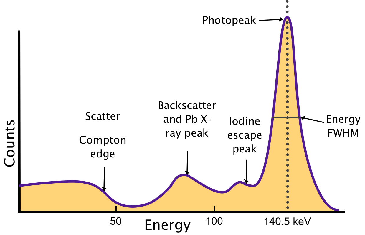
Photopeak: Energy of γ-rays emitted from isotope decay (e.g. 140.5 from 99mTc), spread caused by imperfect energy resolution, characterized by the energy full-width half-max (FWHM) of the peak.
Iodine escape peak: From photoelectric interactions with iodine atoms in NaI crystal. The escape of characteristic iodine K-x-ray, ~28 keV, results in some counts at an energy Eγ - 28 keV.
Lead (Pb) x-ray peak: From photoelectric interactions of γ-rays with lead shielding, which then emits 72- to 87-keV characteristic x-rays. If coming from K-L transition, energy of released γ-rays is 72 keV
Backscatter peak: detection of γ-rays scattered toward detector after 180-degree scattering outside detector. Intensity depends on detector configuration. Energy of scattered γ-ray, $E_b$, and the energy of the recoil electron (Compton edge), $E_{ce}$, sum to the γ-ray energy $E_\gamma$ $$E_b + E_{ce} = E_\gamma$$
Annihilation and double/single escape peaks (not shown): For γ-rays with energy > 1.022 MeV, pair production interactions are possible. The positron-electron pair will then have energy Eγ - 1.022 MeV. Positron will annihilate with electron and create 511-keV photon pairs. If both detected, then event is within photopeak, if one escapes, then there are counts at Eγ - 511 keV (single escape peak). If both escape, then there are counts at Eγ - 1.022 MeV (double escape peak).
Random sums: Two γ-rays happen to hit detector at same time, resulting in counts at twice the expected energy. Magnitude depends on source intensity and timing resolution.
Coincident sums: Occurs for isotopes where multiple γ-rays are emitted on each decay, and two are simultaneously detected (convolution of the two responses).
Count rate shift: change in gain after sudden change in counting rate.
Single channel analyzer (SCA) has a single interval, outputs are identical square pulses (no longer have energy info). Lower-level discriminator (LLD) and upper-level discriminator (ULD) used to establish voltage window. Uses an anti-coincidence circuit: if LLD is exceeded but not ULD, then the event is within the desired energy. Can drive counters and rate meters. If no ULD, then called a discriminator (reject low-level noise).
Multichannel analyzer (MCA) can sort multiple pulses into predetermined voltage ranges/"channels" using a ADC. Spectroscopy. Produce pulse-height-spectra (counts per channel aka energy).
Wilkinson type ADC: Ramp. Input pulse from amplifier causes charge deposition on capacitor. Charge ∝ energy. Discharge through resistor with long RC time constant. During discharge, gate pulse activates clock oscillator to create chain of pulses to counting circuit. Number of pulses (discrete) depends on discharge time depends on charge on capacitor, depends on amplitude of input pulse. MCA adds a count to the memory channel for that number of clock pulses.
Successive approximation type: Compare pulse amplitude to selected sequence of voltage levels. First compared to half of maximum test voltage. Set bit to 1 if higher, 0 if lower. Increase/decrease comparator voltage to half again the higher or lower interval (25% or 75% of max test voltage). Compare again, set second bit. Repeat several time. Get a set of bits representing the amplitude.
Binary number between 0 and 2n for both types, where n is the number of digital levels. E.g. 8-bit has 256 digital levels. More levels, more precise, but more time and computer space. Nuclear medicine uses 10- and 12-bit when precision is needed.
Time is required to do digital conversion, increment memory location, reset clock, etc. Could result in count rate limits.
Timing and Coincidence circuits:
Time-to-amplitude converters (TACs): convert time between pulses to a proportional voltage - one pulse starts current collection, next pulse stops it, voltage at capacitor is proportional to time between pulses.
Leading edge: output pulse occurs at fixed time after the pulse passes a lower level discriminator. Depends on amplitude of input pulse ("timing walk").
Zero-crossover. input bipolar pulse, output pulse occurs at time of cross over from positive to negative voltage. Less sensitive to pulse amplitude.
Coincidence circuit: Produces pulse only if two or more inputs occur within a designated time window.
Sum the input pulses, pass through discriminator set just below the sum of the two. If pulses overlap in time, there will be an output pulse. Timing window is twice the width of the input pulses. Can be used for coincidence detection in PET (but event times are typically compared digitally).
Recording Devices
Scaler-timer/"Counter": Counts pulses and controls counting time. Displayed in visual readout or set to computer for data processing. Uses a gate to control mode of operation. When open, pulses pass to decimal counter assemblies (DCA), each recording 0-9 events. 10th pulse resets first DCA, and starts next. Six DCA can count up to 1-million (999,999).
Can count for a prescribed time (preset-time) or number of counts (preset-count, PSC). PSC allows for statistical reliability (need to be able to record counting time).
Count rate usually 20-50 MHz (pulses spaced 50 to 20 nsec apart) with < 1% losses from pulse overlap.
Analog rate meter: Determines continuous average number of events per unit time. Output is varying voltage proportional to average pulse rate. Used in radiation monitors.
Pulses shaped into constant amplitude and width, which then deposits fixed charge on a capacitor. Discharge rate is τ = RC.
Voltage is proportional to pulse rate: $V = k\bar{n}QR$ where $k$ is amplification, $Q$ is charge, $R$ is resistance, and $\bar{n}$ is the average number of pulses per second.
Changes in pulse rate do not show up instantaneously (usually need 3-5 x τ).
Cathode Ray tube: Used in oscilloscopes and older nuclear medicine systems. Vacuum tube with cathode to supply electrons, anodes to accelerate and focus, plates to deflect horizontally and vertically, and a phosphor screen behind glass to capture electron beam and emit light.
Oscilloscope: Analog: Display done with cathode ray tube. Digital: Fast ADC to digitize waveforms, LCD screen. Need to put into persistence mode to mimic analog phosphor display of multiple pulses. Can also store pulses in memory.
