Nuclear Medical Physics
- Scintillation cameras
- Image acquisition and reconstruction
- Common radionuclides
- SNR, subject/image contrast
- Spatial resolution
- Mechanical aspects: accuracy, precision
- Single Photon Emission Computed Tomography (SPECT)
- Positron Emission Tomography (PET)
- Modality comparison, image features, and artifacts
- Image processing and analysis
- Hybrid imaging (SPECT/CT, PET/CT, PET/MR)
- Radiopharmaceuticals
- Non-imaging devices (dose calibrators, well counters, survey meters)
- Therapeutic NM
- Applications, dose, facilities, and safety
- Internal Radiation Dosimetry
- Methods of quality control and quality assurance
- Counting principles
- Physical, biological, and effective half-life
- Decay calculators
IN PROGRESS
Scintillation cameras
Scintillation is achieved through the use of crystals. See the instrumentation section on scintillation for other details.
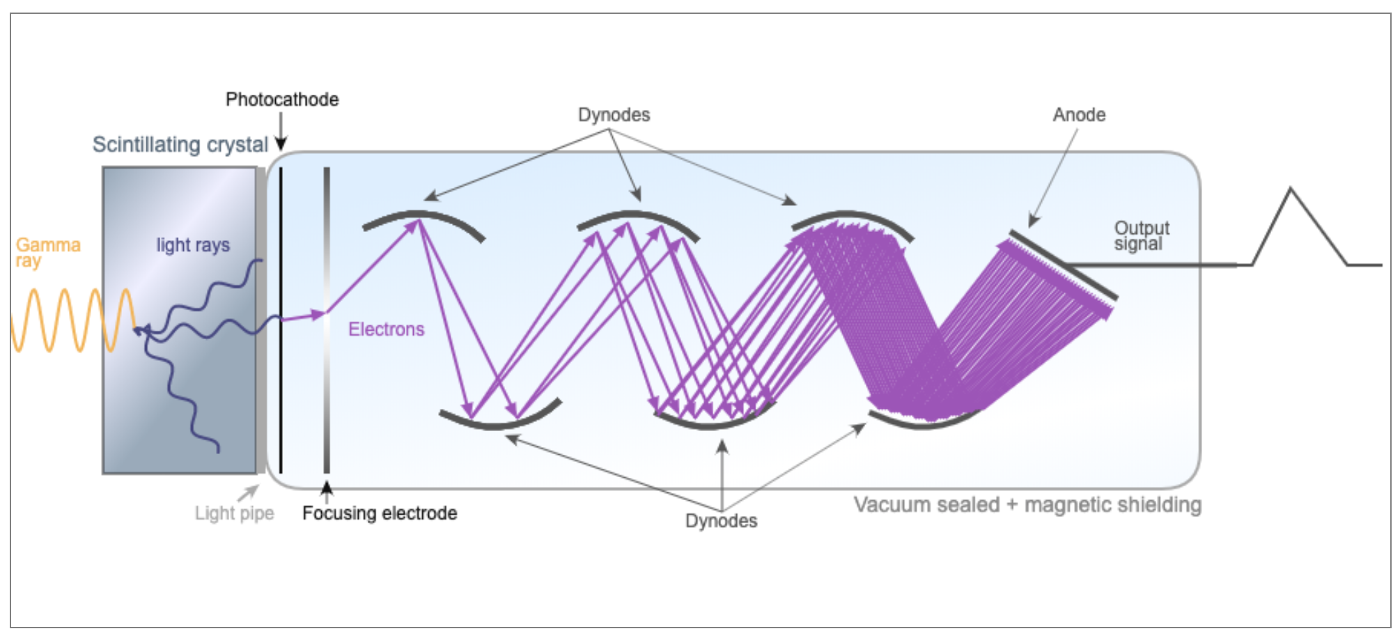
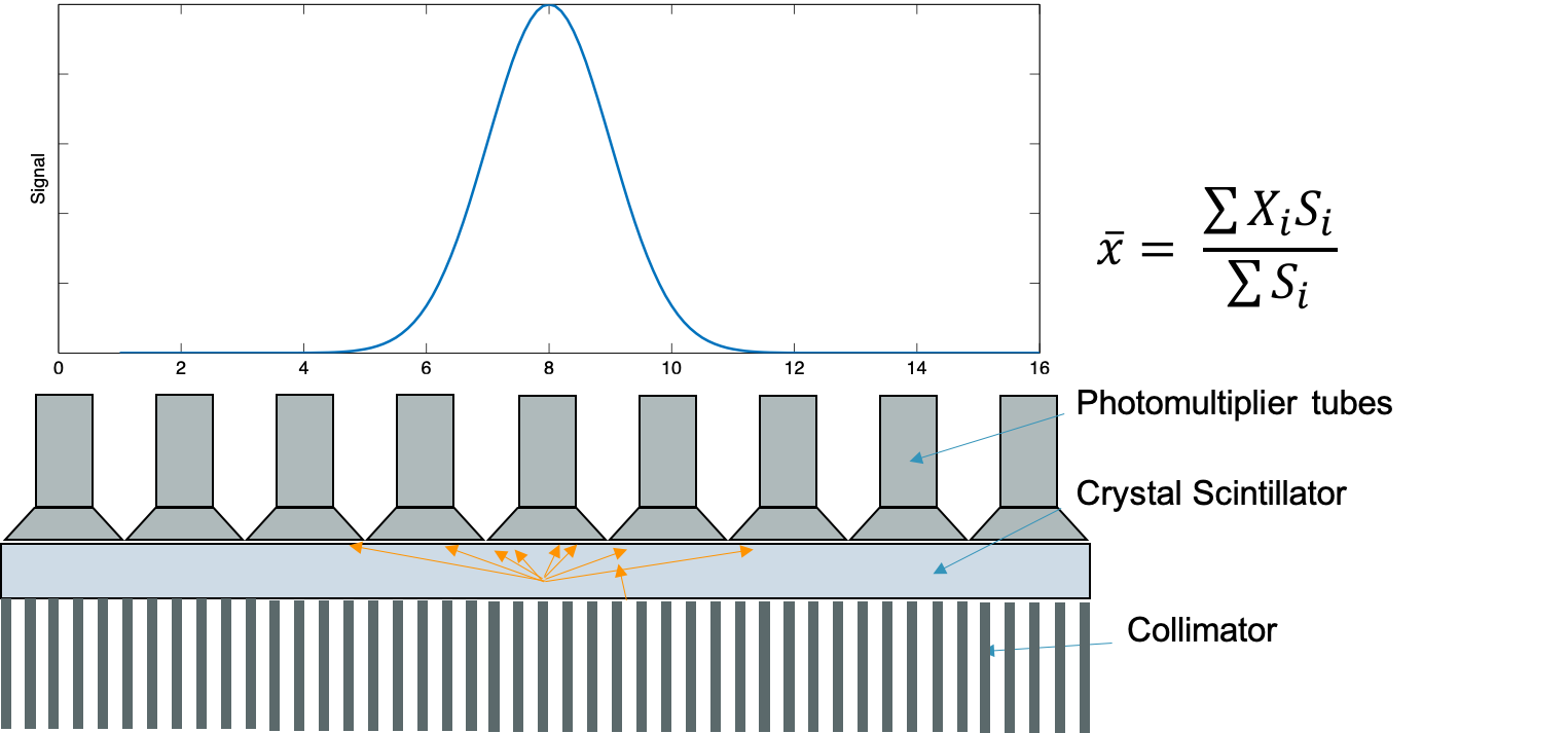
Scintillation is used for gamma cameras, SPECT, and PET. Typically a scintillating crystal is coupled to a photomultiplier tube or solid state photomultiplier to convert the light photons into an electrical signal.
Expand scintillation details
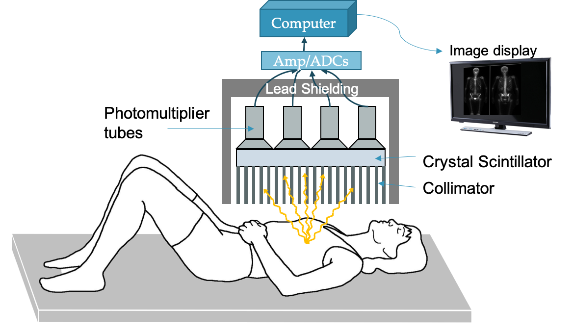
Anger cameras can be used to generate planar images of subjects that have been injected with high energy (~80-400 keV) photon-emitting radioisotopes.
Components:
- Patient: injected with radioisotope that emits photon isotropically
- Collimator: thick lead or tungsten block with holes to allow photons through
- Allows for correlation between location of emitted photon and location of light scintillation
- Scintillator: Typically a large NaI(Tl) crystal that converts the gamma ray into light photons
- PMT array: photomultiplier tubes to collect light photons and convert to electrical signal
- Electronics: preamp, pulse-height analyzer, analog to digital converter
- Computer processor: create image with pixels corresponding to number of photons collected
Scintillator details
Typically NaI(Tl), Cs(Tl), LaBr3(Ce). Most cameras use NaI(Tl) because it is cheap (but fragile)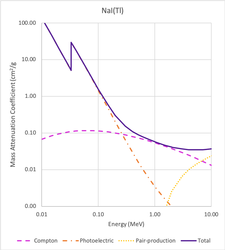
3/8" thick Na(Tl) crystal ideal for 100-200 keV photons (>80% efficiency).
Na(Tl) useful for < 250 keV. Above a Compton scatter starts to dominate (need larger volumes).
Surrounded by reflective surfaces to maximum light onto PMTs, and hermetically sealed to prevent water damage..
Intrinsic spatial resolution: ability to localize events and distinguish between two close locations
Depends on Poisson statistical uncertainty in the number of scintillation light photons collected by PMTs.
Number of photons emitted is proportional to γ-ray energy.
Lower energy → fewer photons in signal → statistical uncertainty → blurring
Spatial FWHM (%) ∝ 1/√E
Light spread also affects resolution: thicker crystal → more chance for light to spread → blurring
Tradeoff between efficiency (thicker crystal, stop more γ-rays) and resolution (thicker crystal, more light spread).
Intrinsic resolution ~ 3.5 mm FWHM for 140 keV photons (99mTc) in 3/8” NaI
Energy Resolution: ability to distinguish the energy of incoming γ-rays
Depends Poisson statistical uncertainty: $\sigma = \sqrt{N}$
Relative uncertainty, ~ 1/√N, goes down with higher counts (more light, higher N).
Energy resolution improves with γ-ray energy: FWHM (%) ∝ 1/√E
Energy resolution is typically around 10% (e.g., for 99mTc with 140 keV γ-rays)
|
Effective Z |
Density (g/cm3) |
Attenuation at 140 keV (cm-1) |
Max emission (nm) |
Decay time (ns) |
Light yield (photons/keV) |
Hygroscopic |
|
|
NaI(Tl) |
50 |
3.67 |
3.12 |
415 |
230 |
38 |
Very |
|
CsI(Tl) |
51 |
4.51 |
4.53 |
540 |
680, 3340 |
65 |
Slightly |
|
LaBr3(Ce) |
47 |
5.30 |
3.42 |
358 |
35 (90%) |
61 |
Very |
PMT array
See PMT page for details on how PMTs work
PMT pulse is proportional to the amount of light scintillation.
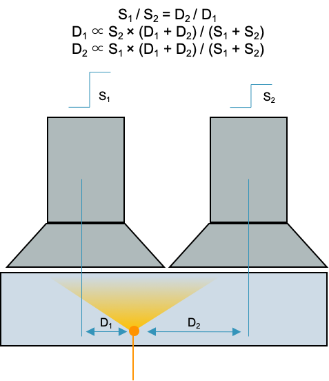
The amplitude decreases linearly with lateral distance from event: S ∝ 1/D
Thus is it possible to use the relative signal in neighboring PMTs to localize an event (gamma photon to light photons)
"Anger logic": $\bar{x} = \dfrac{\sum{X_i S_i}}{\sum{X_i}}$
Essentially finds the center of "mass" of the light collected from various PMTs to localize the gamma ray
Electronics
Processes the location of the signal. Corrects for non-linearity. Determines energy original gamma ray. Sums all PMT pulses.
Pulse height analyzer (PHA): determines valid events based on amplitude of the energy signal (proportional to γ-ray energy). Events with energies outside the designated window are not included in image.
Upper and lower thresholds for valid events are defined slightly wider than the energy resolution, e.g., 15% window around the photopeak for a system with 10% energy resolution (some variation in scintillation light and PMT gain).
PHA helps exclude scatter events, collimator penetration, pileup (coincidence summing).
Collimator
Necessary to determine position of single photons emitted.
Septa, usually lead or tungsten, stop most photons that do not travel in the directions of the holes.
- Parallel hole
- Most common
- Image and object size the same
- Diverging
- Minifies (image is smaller than object)
- Converging
- Magnifies objects (small organs)
- Improves resolution
- Pinhole
- Magnifies
- Small objects only
- Thyroid
Penetration of collimator depends on dimensions of holes, septa material, γ-ray energy
Typically aim for < 5% penetration for a given isotope-collimator system
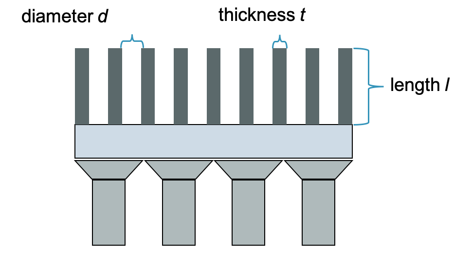
Septal thickness t:
$t ≥ (6 d/\mu) / (l-ln(0.05)/\mu)$
- d = hole diameter
- l = hole length
- μ = linear attenuation coefficient
- Energy dependent
Collimator resolution:
$R_{coll} \approx d \cdot (l_{eff} + b) / l_{eff}$
- d = hole diameter
- b = source distance
- leff = effective hole length
- l - 2μ-1
- μ = linear attenuation coefficient
- Energy dependent
Collimator is the limiting factor in the system spatial resolution:
System spatial resolution: $R_{sys} = \sqrt{R_{int}^2 + R_{coll}^2}$
It also largely determines the efficiency of the system: ~99.9% of incident rays are absorbed by collimator
$g = K^2 * (d/l_{eff})^2 * [(d^2/(d+t)^2]$
- K = ~0.24 round, ~0.26 hexagonal, ~0.28 square
- leff = effective hole length = l - 2μ-1
- d = hole diameter
- t = septa thickness
Increasing efficiency of collimator worsens spatial resolution, and vice-versa: Efficiency ∝ (Rcoll)2
Isotopes that emit higher energy photons need collimators with longer and thicker septa to keep penetration to 5%, but larger holes to maintain efficiency → lose resolution.
Image acquisition and reconstruction
For PET and SPECT, acquisition involves collecting multiple projections. To create 3D images, those projections are reconstructed.
Expand acquisition and reconstruction details
Gamma cameras use Anger logic to determine the location of an event.
PMT pulse is proportional to light scintillation and light scintillation is inversely proportional to the distance of the event to the PMT: S ∝ 1/D
The ratio of PMT intensities and relative locations determine the position of the event ("center of mass" calculation)
$\bar{x} = \frac{\sum{x_i S_i}}{\sum{S_i}}$
Images need corrections for geometry and nonuniformity in detection efficiencies. Typically done with a scan of a uniform source over the detector head. Signal is typically higher directly under PMT face and lower between PMTs, resulting in a large polka dot pattern that is corrected.
Tomographic reconstruction
3D images require reconstruction techniques, slices can be viewed without overlapping structures, improving contrast and quantitation.
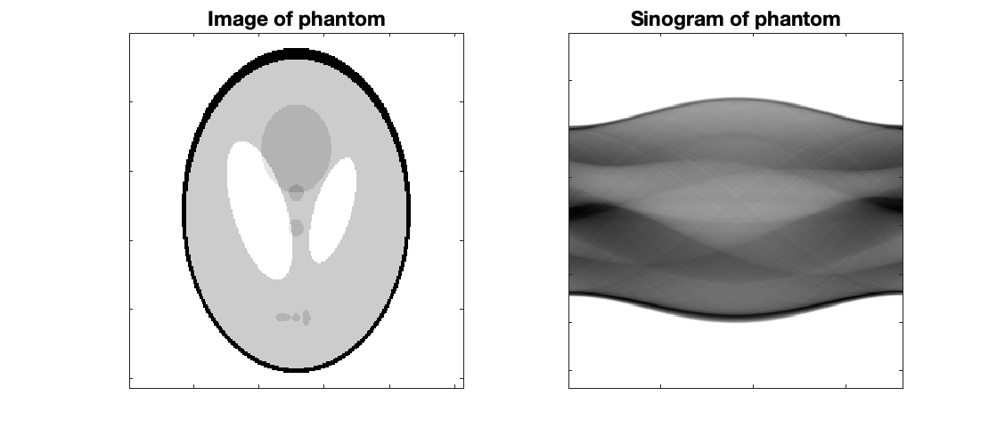
Sinograms
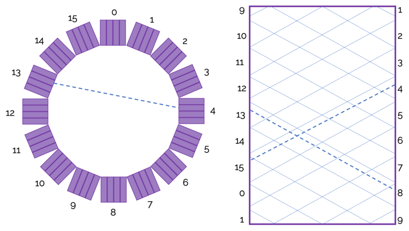 Sinograms are the initial set of "images" generated from detected events. There is typically a sinogram for each slice, and they give the number of counts for a given radial distance and angle. In image above, the angle is the x-axis and radial distance is the y-axis. Diagonal lines represent a detector block pair.
The figure to the right shows how a line of response shows up on a sinogram.
Projections are an alternative visualization that will display slice vs view.
Filtered Back Projection (FBP)
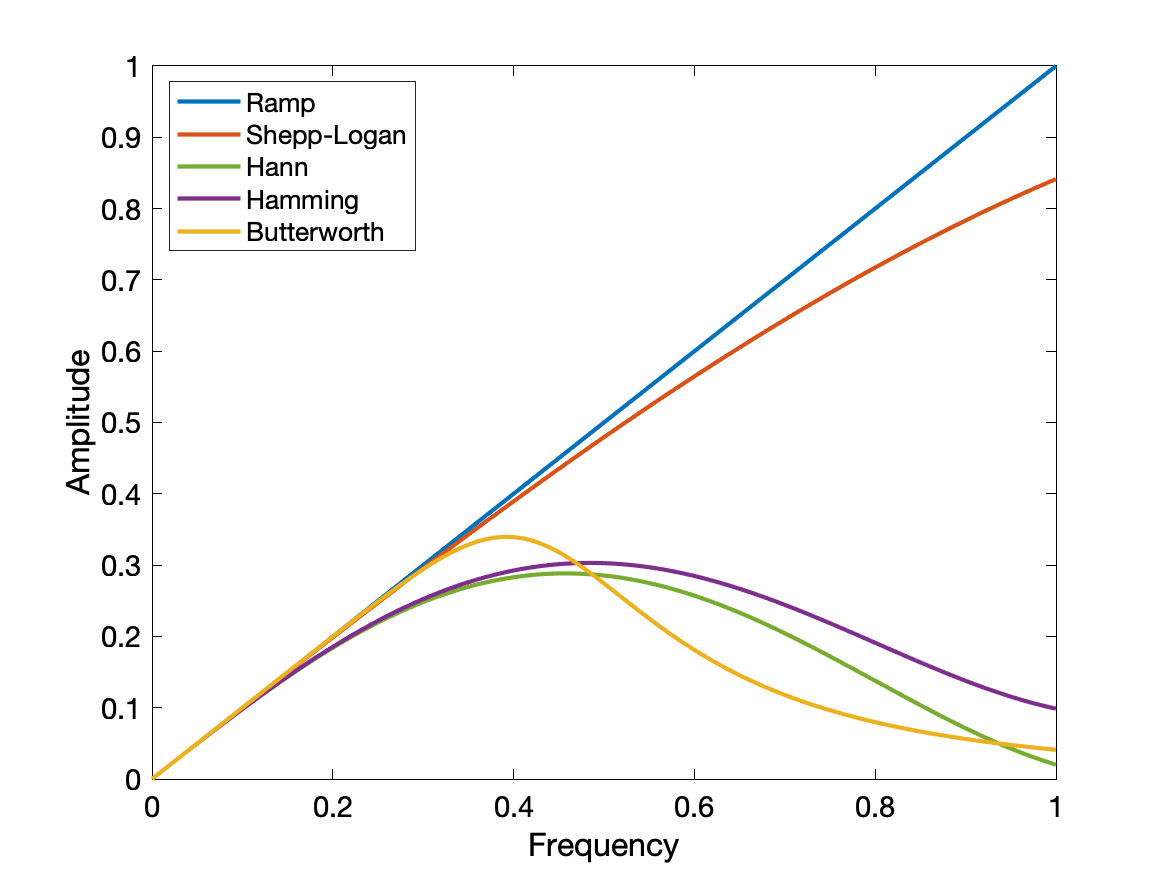 FBP first involves a Fourier transform into spatial frequency space, filtering the sinogram to remove low frequencies (reduce the 1/r blurring) and very high frequencies (reduce noise), and then an inverse Fourier transform. The sinograms are back-projected into an image using a Radon transformation.
Filter types include ramp (zero at zero frequency, linearly increasing to a cutoff frequency). Shepp-Logan, Hann, Hamming, and Butterworth. Each filter has a few modifiable properties to further define its shape and emphasize low noise vs high contrast, as desired.
Excellent visualization of FBP in gifs
Iterative reconstruction
E.g. Maximum-Likelihood Expectation Maximum (MLEM) and Ordered Set Expectation Maximum (OSEM)
Simplified diagram of how iterative reconstruction works:
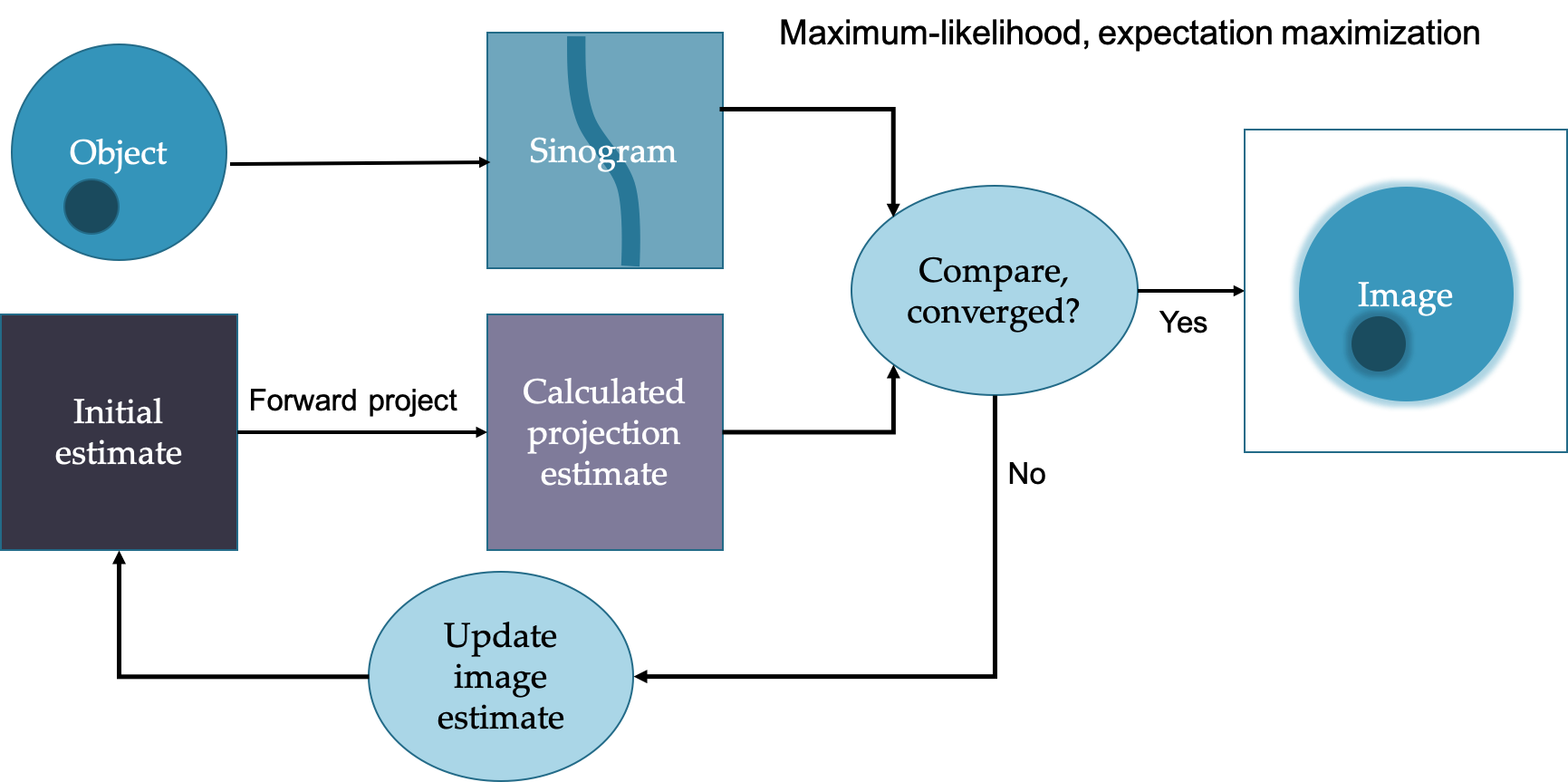 In general more iterations leads to sharper images but more noise. Often subsets are used to speed up the process. Can more easily incorporate corrections such as attenuation and scatter and geometric considerations.
Image task often guides the determination of image quality and ideal reconstruction. E.g., want to estimate myocardial wall thickness, prefer good resolution over low noise, but want to detect metastases, want high contract and low noise (reduce false positives).
Common radionuclides
Below are some common radionuclides that are used in PET/NM imaging and therapy applications.
Expand radionuclide details
Positron-emitting radioisotopes (imaging)
|
Isotope |
Half life |
Production method |
Decay mode, photon energies |
Uses |
|
C-11 |
20.3m |
Cyclotron |
β+, 511 |
Radiotracer in PET scans to study normal/abnormal brain functions. |
|
Cu-62 |
9.7m |
Generator (Zn-62) |
β+, 511 |
Positron emitting radionuclide, cerebral and myocardial blood flow used As-a tracer in conjunction with Cu 64. |
|
Cu-64 |
12.7h |
Cyclotron |
ec, β-, β+ (19%), 511, 1340 |
PET scanning, planar imaging, SPECT imaging dosimetry studies , cerebral and myocardial blood flow, used with Cu-62 , treating of colorectal cancer. |
|
F-18 |
110m |
Cyclotron |
β+, 511 |
PET cancer imaging, brain studies |
|
Ga-68 |
68.1m |
Generator (Ge-68) |
ec, β+, 511 |
Study thrombosis and atherosclerosis, PET imaging, detection of pancreatic cancer, attenuation correction. |
|
Ge-68 |
271d |
Cyclotron |
β+, 511 |
PET imaging (phantoms) |
|
N-13 |
9.97m |
Cyclotron |
β+, 511 |
PET imaging, myocardial perfusion. |
|
O-15 |
122s |
Cyclotron |
β+, 511 |
Water used for tomographic measuring of cerebral blood flow , PET imaging , SPECT imaging. |
|
Rb-82 |
1.27m |
Generator (Sr-82) |
ec, β+, 511 |
Myocardial imaging agent, early detection of coronary artery disease, PET imaging, blood flow tracers. |
Photon-emitting radioisotopes (imaging)
|
Isotope |
Half life |
Production Method |
Decay mode, photon energies |
Uses |
|
Ga-67 |
78.3h |
Cyclotron |
ec, 93, 185, 300 |
abdominal infections, detect Hodgkins/non-Hodgkins lymphoma, used with In-111 for soft tissue infections and osteomyelitis detection, evaluate sarcoidiodis and other granulomaous diseases (lungs and mediastiusim) |
|
I-123 |
13.1h |
Cyclotron |
ec, 159 |
Brain, thyroid, kidney, and myocardial imaging, cerebral blood flow, neurological disease (Alzheimer's). |
|
In-111 |
2.81d |
Cyclotron |
ec, 171, 247 |
Detection of heart transplant rejection, imaging of abdominal infections, antibody labeling cellular immunology, used with Ga-67 for soft tissue infection detection and ostemyelitis detection , concentrates in liver, kidneys, high specific activity, white blood cell imaging, cellular dosimetry, myocardial scans, treatment of leukemia, imaging tumors. |
|
Tc-99m |
6.01h |
Generator (Mo-99, from fission) |
IT, 40 keV |
Brain, heart, liver (gastoenterology), lungs, bones, thyroid, and kidney imaging , regional cerebral blood flow , equine nuclear imaging , antibodies , red blood cells , replacement for Tl-201 . |
|
Tl-201 |
73.1h |
Cyclotron |
ec, ~70, 166 |
Clinical cardiology, heart imaging, less desirable nuclear characteristics than Tc-99m for planar and SPECT imaging, myocardial perfusion, cellular dosimetry. |
|
Xe-133 |
5.25d |
Nuclear fission |
β-, 81 |
Lung imaging, regional cerebral blood flow, liver imaging (gas inhalation), SPECT imaging of brain, lung scanning, lesion detection. |
Therapeutic radioisotopes
|
Isotope |
Half life |
Production Method |
Decay mode, photon energies |
Uses |
|
I-125 |
59.9d |
Neutron activation |
ec, 27-30 |
In Vitro, Osteoporosis detection, diagnostic imaging, tracer for drugs, monoclonal antibodies, brain cancer treatment (I-131 replacement), SPECT imaging, radiolabeling, tumor imaging, mapping of receptors in the brain, interstitial radiation therapy (brachytherapy) for treatment of prostate cancer. |
|
I-131 |
8.04d |
Nuclear fission |
β-, 364 |
Lymphoid tissue tumor/hyperthyroidism treatment, antibody labeling, brain biochemistry in mental illness, kidney agent, thyroid problems, alternative to Tl-201 for radioimmunotherapy, imaging, cellular dosimetry, scintigraphy, treatment of graves disease, treatment of goiters, SPECT imaging, treatment of prostate cancer, treatment of hepatocellular carcinoma, treatment of melanoma, locate osteomyelitis infections, radiolabeling, localize tumors for removal, treatment of spinal tumor, locate metastatic lesions, treAt-neuroblastoma, internal (systemic) radiation therapy, treatment of carcinoma of the thyroid. |
|
Lu-177 |
6.68d |
Neutron activation |
β-, 208 |
Heart disease treatment (restenosis therapy), cancer therapy. |
|
Sm-153 |
2.00d |
Neutron activation |
β-, 41, 103 |
Cancer treatment/diagnostics, monoclonal antibodies, bone cancer pain relief, higher uptake in diseased bone than Re-186, treatment of leukemia. |
|
Sr-89 |
50d |
Neutron activation |
β-, 1492 |
Bone cancer pain palliation (improves the quality of life), cellular dosimetry, treatment of prostate cancer, treatment of multiple myeloma, osteoblastic therapy, potential agent for treatment of bone metastases from prostate and breast cancer. |
|
Y-90 |
64h |
Generator (Sr-90) |
β- |
Internal radiation therapy of liver cancer, monoclonal antibodies, Hodgkins disease, and hepatoma, cellular dosimetry, treating rheumatoid arthritis, treating breast cancer, treatment of gastrointestinal adenocarcinomas. |
(additional radioisotopes are used in brachytherapy as sealed sources)
Quality control isotopes
|
Isotope |
Half life |
Production Method |
Decay mode, photon energies |
Uses |
|
Co-57 |
272 days |
Cyclotron |
ec, 122 keV |
Quality control for gamma/SPECT cameras, close in energy to Tc-99m |
|
Gd-153 |
241.6 days |
Reactor |
ec, 100 keV |
Quality control for gamma/SPECT cameras, uses 100 keV gamma, attenuation mapping |
|
Ge-68 |
271 days |
Cyclotron |
ec to β+, 511 |
Quality control for PET cameras, in equilibrium with daughter Ga-68, imaging the β+ from Ga-68 |
|
Cs-137 |
30 years |
Nuclear Fission |
β-, 661 |
Quality control for dose calibrators (constancy) |
Radioisotopes from cyclotron are generally carrier free because it is possible to separate the product isotope from the target (different p = different elements).. β+ emission, electron capture.
Radioisotopes from fission can generally be separated chemically but because of other fission products the radionuclidic purity may be low. Many decay mechanisms.
Radioisotopes from neutron activation cannot be easily separated because the products are not different elements (chemically similar). Often low specific activity and not carrier-free. β- emission.
SNR, subject/image contrast
Signal-to-noise ratio (SNR) is a measure of how far a lesion protrudes above (or below) the average background level. Contrast is a measure of differences in brightness, counts, or optical density in adjacent regions Both are import image quality metrics, especially for nuclear medicine.
Expand image quality details
Signal-to-noise ratio (SNR) is a measure of how far a lesion protrudes above (or below) the average background level. A lesion SNR of about 2 would be marginally detectable. SNR of 3-5 is required for detectability ("Rose criterion").
SNR is essentially a ratio of the mean over the standard deviation: $SNR = \mu / \sigma$
For Poisson statistics, this is $\sqrt{N}$. For reconstructed images the SNR of a pixel is less straightfoward: $SNR_{pixel} = \sqrt{\frac{12 N}{\pi^2(D/\Delta r)^3}}$ where $\Delta r$ is the pixel size and $D$ is the matrix size.
Contrast: measure of differences in brightness, counts, or optical density in adjacent regions
$\frac{S_a - S_b}{0.5(S_a + S_b)}$ or $\frac{S_a - S_b}{0.5( S_b)}$
Subject contrast: contrast inherent in the image information, independent of the means of display.
Displayed contrast: varies with means of capturing image and displaying image. E.g. film response curve, gray scale/color scale used, window/level.
Dynamic range: total range of counts that can be recorded between min and max brightness ("latitude" in film).
Image contrast decreases with increasing noise.
Contrast-to-noise (CNR) is a measure of contrast between objects relative to the noise in the background.
$CNR = \frac{S_a - S_b}{\sigma_o}$ where $S_a$ and $S_b$ are the signal intensities of structure $a$ and $b$ and $\sigma_o$ is the standard deviation of the image noise.
Contrast is reduced for smaller objects, depending on the systems spatial resolution.
PET and SPECT are susceptible to partial volume effects. Activity can only be recovered full for objects at least 2x the FWHM of the image. 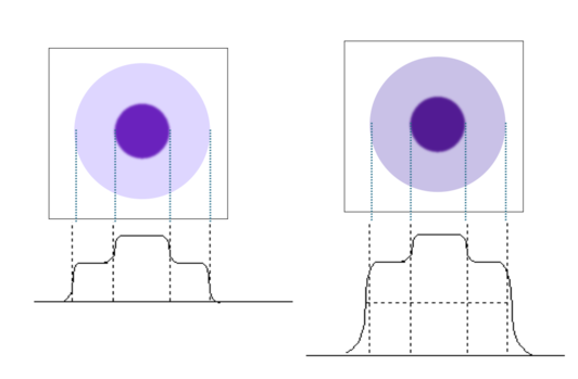
Additional background counts (e.g. from scatter and randoms) reduce lesion contrast. The relative height of the object to background decreases. Scatter is one of the most significant sources of contrast loss in nuclear medicine.
Spatial resolution
Spatial resolution is an important imaging metric, especially in PET/NM, where resolution tends to be much lower than for CT and MRI anatomic images.
Expand spatial resolution details
Resolution is a measure of how close two lines or objects can be to each other and still be visibly resolved as distinct objects. In nuclear medicine, resolution is usually given as the full width at half maximum (FWHM) of a point or line source, Sources typically have a Gaussian distribution, such that FWHM = 2.355 σ. 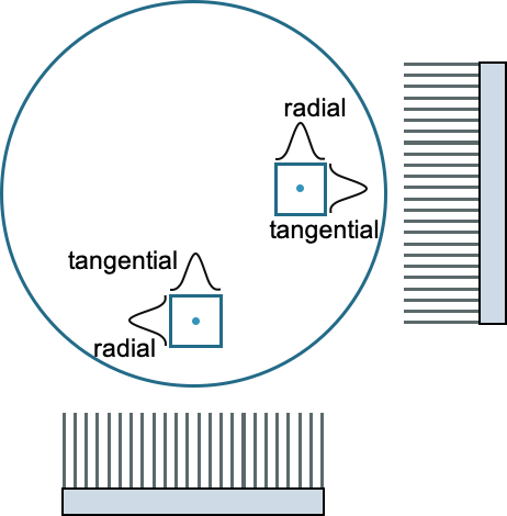
Resolution is measured in both the axial (along the bore or the axis of rotation) and transaxially. Transaxial resolution is a combination of tangential and radial (parallel and perpendicular to the crystal face).
Resolution is partly determined by the system design, in terms of crystal types, sizes, PMT types and sizes, collimation, etc.
PET spatial resolution is typically 3-7 mm. Two physical factors limit system resolution: positron range and non-collinearity of the photons. It is also affected by the detector size and configuration.
SPECT spatial resolution is typically around 12 mm. The main limiting factor is the collimator.
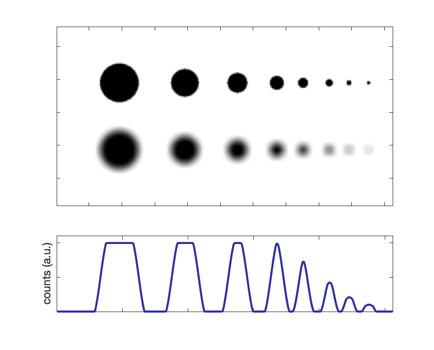
Partial volume effect: Intensity and apparent activity concentration decrease with smaller object sizes. See figure to the right for an illustration of various size objects, along with a degraded resolution version and corresponding line profile.
For object sizes ~ 2 × FWHM, activity concentration can be fully recovered.
There is a constant trade-off between spatial resolution and sensitivity.
See also modulation transfer function (MTF).
Mechanical aspects: accuracy, precision
Rotation in SPECT and CT alignment to SPECT and PET are important for accurate imaging. Both involve precise mechanical movements of the bed and or gantry.
Expand mechanical aspects details
Because of the physical rotation used in SPECT imaging (and not in PET), there are a few more considerations: the center of rotation must coincide with the image reconstruction center. Monthly tests are done with point sources to ensure proper functionality.
Gravity has a non-negligible effect on the detector heads, so they have the potential to respond differently depending on orientation.
For both PET/CT and SPECT/CT tests must be done (at acceptance) to ensure the two images are in alignment for proper attenuation correction and anatomical localization.
More details to come!
Single Photon Emission Computed Tomography (SPECT)
By combining planar images from various angles it is possible to generate a 3D image of the radioactivity distribution and remove the overlapping of structures seen in planar images (similar to x-ray vs CT).
Projections are acquired at regularly spaced intervals (or continuously) over at least 180 degrees.
Expand SPECT details
SPECT imaging can be done with one, two, or three heads, but two is most typical. Imaging less than 180 degrees can result in artifacts.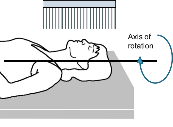 Motion of detector heads can be circular or oblique (to minimize distance to object and maximize resolution).
Many slices are acquired at each angle, e.g., 256 x 256 matrix acquires 256 linear samples of the transverse plane for 256 axial slices.
Reconstruction of the projections is usually done with filtered back projection (similar to how CT if often reconstructed) or with an iterative algorithm.
Each event is placed into a "sinogram" based on the location on the detector head and its current angle. Those sinograms are back-projected into image space (usually after some filtering out of low and very high frequencies to reduce blurring and noise).
Excellent gifs of the reconstruction process can be found on Kesner's Medical Physics.
Corrections:
Aside from the usual corrections to the planar images, additional corrections for scatter and attenuation can be made to improve image quality.
Anatomical information for attenuation can be gathered from a separate transmission image (using a different photon energy, e.g., Gd-153 at 97 and 103 keV) or from a CT scan in the case of SPECT/CT. Those images are used to estimate the ratio of transmission relative to a blank scan.
Attenuation correction factor:
- ACF = $I_{transmitted}/I_{incident} = I/I_0 = e^{-μd}$
- $d$ is the depth in tissue, but it is different for each projection angle
- Each pixel may have a different density and effective Z (thus $μ$)
- $μ$ also depends on the energy of photons - lower energy, more attenuation
- Can use transmission or CT scan to estimate $μ$
ACF: Conjugate counting: Use oppose projections (at 180 from each other) to compensate for different depth in tissue
Relies on geometric mean: $I = \sqrt{I_a \cdot I_b} = \sqrt{I_1 e^{-\mu a} \cdot I_2 e^{-\mu b}}$ where I is intensity of object at depth a and b (from opposite directions) based on intensity, $I_a$ and $I_b$, reaching each detector. $I_1$ and $I_2$ are the initial emitted intensities in both direction (same if using parallel hole collimators).
 The spatial resolution of the SPECT images is typically quite a bit lower than planar, but the contrast is higher. It is usually divided into transverse and axial resolution. Transverse is a combination of tangential and radial.
Axial resolution depends on intrinsic and extrinsic resolution of the detectors, the object-detector distance (depends of radius of rotation), acquisition matrix size and zoom factor,
Transverse resolution depends on intrinsic and extrinsic resolution of the detectors, the object-detector distance (depends of radius of rotation), acquisition matrix size and zoom factor, angular sampling interval (# views per rotation), and the reconstruction algorithm and filter.
Partial volume effect: Intensity and apparent activity concentration decrease with smaller object sizes. For object sizes ~ 2 × FWHM, activity concentration can be fully recovered.
Most common radionuclide used in SPECT is Tc-99m. Half life 6 hours.
Thallium-201 used for cardiac studies. Half life 73.1 hours.
Cardiac scans typically use a dedicated scanner or two detector heads set at 90 deg. This allows to for imaging to be concentrated on the area of interest.
Positron Emission Tomography (PET)
PET uses the annihilation photons from a positron emission to generate tomographic images. A ring of detectors surrounds the object being imaged to collect and process with photons.
Expand PET details
Positrons are emitted from proton-rich nuclei:
p → n + β+ + ν
$^{18}O(p,n)^{18}F$
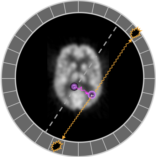
The antiparticle positron (β+) soon finds an electron with which it annihilates into two photons, each sharing half of the combined mass of the two leptons, 511 keV + 511 keV. The photons are emitted in opposite directions, although if the positron had some initial momentum, they won't be at exactly 180°, and the annihilation won't happen exactly where the even occurred. (These details contribute to worse resolution.)
The most common isotopes are C-11, N-13, O-15, F-18, and Rb-82 (list). By far the most common radiotracer is 18F-FDG, a glucose analog that goes to sugar-hungry tumors, inflammation, and the brain. Most isotopes are made in cyclotrons (adds the extra protons), and some come from generators made in reactors.
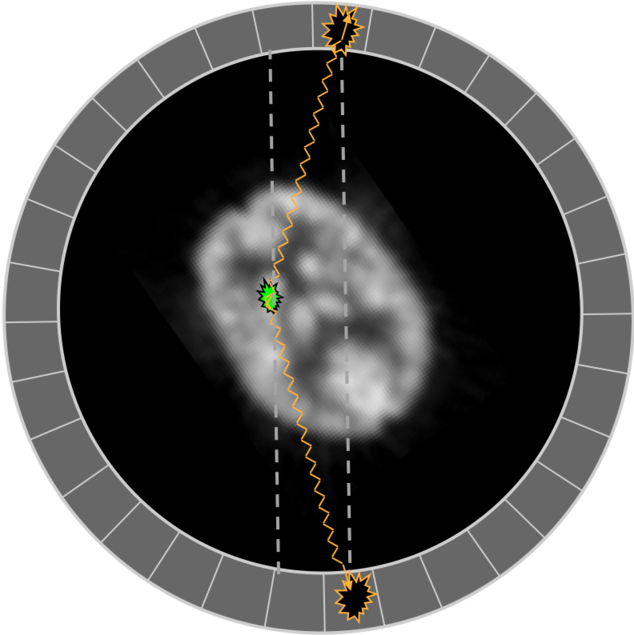
Unlike SPECT, PET does not use physical collimation to localize the photons. The coincidence of the two photons within the PET ring allows for the localization across the "line of response" between the two detectors. Results in much higher sensitivity, since the majority are not stopped by a sheet of lead.
PET detectors use a crystal to convert the 511 keV photons from the positron annihilation into light photons. The light is detected by a PMT or SiPM. The signals are then processed for energy, coincidence, and various corrections. Coincidence requires events from two crystals to happen within a chosen time frame (e.g. 10 ns). Any pair of crystals can potentially be in coincidence, although sometimes there are exclusions, e.g., if crystals are directly adjacent, or from two rings very far apart. To be able to use coincidences, a full 360° set of rings is ideal.
Scintillating crystals used in PET:
|
Scintillator |
Effective Z |
Specific Gravity |
Linear Attenuation Coefficient (cm-1) |
Relative light output |
Scintillation decay constant (nsec) |
Theoretical energy resolution |
Cost |
|
BGO |
74 |
7.13 |
0.92 |
15 |
300 |
~20% |
$$$ |
|
NaI |
51 |
3.67 |
0.34 |
100 |
230 |
~10% |
$ |
|
LSO |
66 |
7.4 |
0.87 |
75 |
40 |
~12% |
\$$$$ |
|
GSO |
59 |
6.71 |
0.62 |
41 |
56 |
~10% |
\$$$$ |
Zeff, Specific gravity, Linear attenuation coeff - Higher, better sensitivity/efficiency → more counts, less noise
Relative light output - Higher, better energy resolution (more statistics) → better scatter rejection
Scintillation decay constant - Shorter, better timing resolution → better randoms rejection, better time-of-flight estimation → higher SNR
Block detectors: a large scintillator piece is cross cut to varying depths, and the slits filled with reflective material. Four PMTs share the block and the depths of the cuts determine how much light each PMT sees. The relative amount seen by each PMT determines the location of the annihilation event (similar to Anger logic). Allows more detector elements to be shared by fewer PMTs and improves spatial resolution. Typically 20-30 mm thick with 4 to 6 mm sub-elements.
Quadrant sharing is used to reduce number of PMTs needed, where each PMT sees parts of multiple different blocks. Can also lead to increased dead time (each PMT see larger volume).
Panels of detectors are arranged in a circle (or hexagon) to create a full PET ring.
Two different scintillating material, with different decay times, can be stacked to get depth of interaction information and improve resolution.
Ideal PET scanner characteristics
- High sensitivity - High Z/density/attenuating crystals, thicker crystals, Time of flight (TOF).
- Good spatial resolution - Small crystals, thiner crystals, more light output. Depth of interaction (DOI) correction
- High count rate capability - Fast crystals
- Low dead-time - Fast scintillation decay and electronics
- Low scatter fraction - 2D mode (but then low sensitivity), good scatter rejection algorithms
- Good energy resolution - High light output crystals
In "list mode", each event is written to a file with time stamp and various other details (e..g, energy). Sinograms can later be generated during the reconstruction process.
In sinogram mode, each event is placed in a sinogram based on the angle of the line of response (LOR) and location in the FOV. Those sinograms are reconstructed using FBP or an iterative method.
Some informative reconstruction gifs can be found on Kesner's Medical Physics.
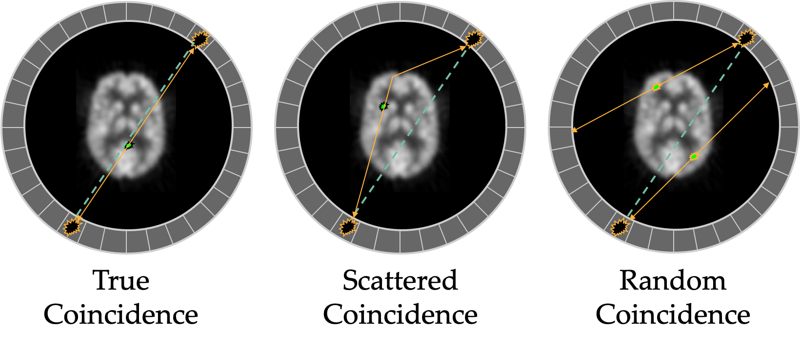
Other events that can occur which are not true coincidences (and reduce contrast) are scatter and randoms.
Scattered events include a photon that scattered in the patient and thus will give the wrong line of response. Scattered photon at angles less than 50 deg may still be within the energy window, larger scatters can be rejected by LLD. Random events are when two annihilations from separate decays happen at the same time and a photon from each is detected and associated. Randoms increase with increased activity (more likely). Scattering depends on the composition and geometry of the object.
 Randoms can be estimated by using a delayed coincidence window to determine how likely random events are occurring between two detectors. The delayed window should have no true coincidences, so it can estimate how many random coincidences are likely occurring during the scan. Randoms increase with higher activity: randoms ∝ (activity)2 (less likely to get two events at same time from different positron emissions) whereas true coincidences increase linearly with activity. Randoms also increase with larger energy and timing windows: $R = 2 \tau C_1 \cdot C_2$ where τ is timing window and Cs are the count rates of the two detectors on the LOR.
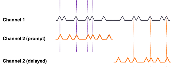
Method for random event correction using a delayed timing window
Scatter can be estimated using multiple energy windows or using the attenuation map and tails in the sinograms from events outside the object (where none should be) in more complex modeling. There are many methods and variations to deal with scatter. Narrower energy windows can help reduce scatter, but may also increase noise by removing some true events. Scatter is typically 30-60% of total counts (in 3D-mode without septa). Scatter contributes to loss of resolution and shift of activity from hot to cold regions.
Attenuation naturally occurs in the patient, and can usually be corrected easily if there is a co-registered CT scan, or a transmission scan, usually Ge-68 rod that rotates to generate a map, similar to CT but with 511 keV photons.
Only the full line of response matters, since the coincidence symmetry means it doesn't matter where along the line the photons are being emitted. Makes the correction easier than with SPECT (along with the attenuation being more uniform at the higher energy 511 keV photons for a variety of tissues).
Mismatch between transmission and emission scans (taken sequentially) can cause artifacts, especially at interfaces between tissues with very different densities.
CT scans are taken with lower energy photons and must be converted using a bilinear correction to the attenuation seen by 511 keV photons (easily done). Transmissions scans are done with 511 keV photons, and thus don't need an energy correction (but are not very useful for anatomical information).
The change in intensity, $I/I_o$, is given by the exponential decay equation $I/I_o = e^{-\mu x}$, where $x$ is the distance traveled, $μ$ is the energy dependent linear attenuation coefficient for a given material.
Factors affecting image quality
Injected activity: more activity, more photons, more signal, less noise. BUT, higher dose to patient and technologists.
Patient size: same activity spread over larger area means less comes from each region. Typically compensated by increasing injected dose and/or scanning longer. Also means more attenuation and scatter, less signal, more noise.
Resolution:
Intrinsic resolution is degraded by positron energy, which determines how far it travels before annihilating, and how close to 180° are the coincidence photons. Less than 180° between the annihilation photons comes from conservation of momentum.
Angular uncertainty is about 0.5 degrees. For 1 m diameter scanner, translates to 2 mm positional uncertainty.
Illustrations of how less than 180 degree collinearity (left) and positron range (right) can affect the detected position of a decay event, and thus resolution.
F-18 mean range in water is 0.1 mm FWHM. Rb-82 range is 1.6 mm, and thus has much worse resolution.
Size of crystal (smaller means better resolution, but lower sensitivity), and size of reconstruction matrix.
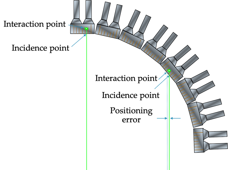
Depth of interaction (DOI) in the crystal. Degrades resolution away from the center, since there is more error in the position vs depth. The effect becomes more significant with smaller crystal rings (e.g. for brain-only PET systems).
Elements contributing to resolution:
$$\text{FWHM} = a \sqrt{(d/2)^2 + b^2 + (0.5*D*\text{tan}(0.25^{\circ}))^2 + r^2}$$
$a$: effects from reconstruction, depends on algorithm and parameters (typically 1.1 to 1.3)
$d$: detector size - geometric factor,
$b$: detector positioning accuracy - coding, depends on light sharing with PMTs/direct coupling (no effect), crystal size
$D$: Distance between coincidence detectors (diameter of ring) - affects non-collinearity (0.9 to 2.0 mm, brain to WB)
$r$: positron range - depends on isotope (~0.5 mm 18F but 2.5 mm 82Rb)
$D$ and $r$ are partly intrinsic factors (~1 mm brain scanner ~2 mm whole body), and $D$, $d$ and $b$ are detector factors (3-4 mm). Total typical FWHM ~ 4.5-7 mm.
Time-of-flight
Faster crystals (e.g. LYSO) , possible to narrow down likely location of annihilation event. Event is only projected to likely voxels rather than entire line of the response → statistical noise only propagated to a few nearby voxels → improves Signal to Noise Ratio (SNR).
Typically timing resolution around 500 ps → 7.5 cm spatial uncertainty.
Quantitation
PET is typically a quantitative imaging modality (in contrast SPECT and MRI are usually not). With the proper corrections, it is possible to translate image intensities into activity concentration - activity per unit mass. Voxels in images are usually given in kBq/ml. For quantitation purposes, activity concentrations are often converted into Standard Uptake Values (SUV). This is because more dose injected will naturally lead to higher activity concentrations, so SUV normalizes by injected dose concentration. This can be useful for repeat scans looking for progression/regression.
SUV = activity concentration in image / (injected activity/mass of patient)
Units: g/ml (essentially unitless)
Note: SUV is overestimated in patients with higher body fat because fat does not concentrate much FDG.
This can be mitigated by using body surface area, which is more difficult to estimate.
Imaging radiotracers
FDG
FDG is used in over 90% of PET scans. It is valuable because it behaves initially like glucose, but is captured in cells because it doesn't go through the full metabolic pathway. Thus, after uptake of 30-60 minutes, most of the tracer has gone to areas of high glucose use and stayed there.
FDG is transported intracellularly by the GLUT1 transporter and metabolized by hexokinase and glucose-6-phosphatase (same as glucose), but because it cannot undergo glycolysis, it remains trapped within the cell.
18NaF
Sodium Fluoride, bone remodeling
82Rb
Rubidium, Mycocardial perfusion imaging. Often performed at rest and stress.
13NH3
Ammonia, Mycocardial perfusion imaging. Often performed at rest and stress.
Modality comparison, image features and artifacts
Expand modality comparison details
PET generally has better resolution than SPECT (but each has tracers that may be better for a given indication)
Tomography allows for 3D images (or 2D slices) that eliminates the overlappign structures seen in planar imaging. Planar imaging typically has better resolution than 3D, but worse contrast.
To be continued...
Image processing and analysis
SPECT and PET require reconstruction and NM and PET images often require additional imaging processing and analysis to retrieve diagnostic information.
Expand processing details
This site by Dr Kesner has an excellent set of gifs illustrating the reconstruction process for PET and SPECT
To be continued
Non-imaging devices
Non-imaging devices in NM/PET refer to dose calibrators, well counters, survey meters, etc. These are used for dosing, radiation safety and quantitation purposes.
Expand non-imaging device details
Dose calibrators
Dose calibrators well-type ionization chambers (argon-filled sealed and pressurized chamber) used to measure doses in the mCi / MBq range (i.e. those used for injection in nuclear medicine imaging). Are used for quantities larger than those for scintillation well counters. Measure the total ionization produced by the sample, and display the radioactivity based on chosen isotope type. No photon energy information.
Quality control
- Constancy - daily. Long lived source with single energy peak (e.g., 137Cs), record reading, should not vary more than 10% day-to-day (usually much less)
- Accuracy - installation, annually, after repairs. Measure two long lived sources (e.g. 137Cs, 57Co) calibrated and certified by NIST, compare measurements to NIST reported activity (decay corrected). Should not differ more than 10%
- Linearity - installation, quarterly, after repairs. Test ability to measure over a range of activities.
- Decay method (required at installation): Start with activity (e.g. 99mTc) at highest activity used clinically. Measure at several time intervals (e.g. ~every half life) until it reaches 30 μCi = 1.1 MBq. Plot activity vs time on semi-log, fit line, Any deviations greater than 10%, need repair/replacement, or correction in non-linear region.
- Shielding method (ok for quarterly tests): commercial kit of lead sleeves of varying thickness. Increasing thickness is added with source in chamber, measuring each time, with attenuation simulating decay. Measurements are corrected by calibration factors, and deviations more than 10% require action.
- Geometry - installation, after moving or repairs. Tests the effect of variations in the geometry of sampled measured. Same activity is measured in increasingly large volumes of syringes and vials. Correction factors determined and applied if variations are greater than 10%
- 99Mo breakthrough - when using 99mTc, measure in dose calibrator first with and then without lead sleeve. Lead blocks lower energy Tc photons and allows through higher energy Mo photons. Should have <0.15 µCi 99Mo per mCi of 99mTc.
- Tested with lead first to avoid residual charge lingering
- Precision - Repeat same measurement of same source multiple times in a row to test consistency
Well counters
 Typically a single NaI crystal scintillator with a hole in one end (well-type) for measuring small samples of radioactivity. 4.5 cm x 5 cm with hole of 1.6 cm diameter x 3.8 cm depth. Surrounded by lead to stop background activity. Light from crystal is captured by PMT and converted to electrical signal that counts decays. Energy resolution ~ 10-15% FWHM because of large size and scattering. Geometric efficiency near 100% (larger samples closer to top of hole have lower efficiency). Can count low activities (Bq to kBq). Intrinsic efficiency depends on energy and crystal size (near 100% for small sample, low energies, and 40-80% for higher energies). Calibration can give data in absolute activity. Deadtime (paralyzable) an issue with higher activities (100 to 10000 Bq is good range).
Survey meters
Typically gas chambers in the ionization or GM voltage range. Give readings in exposure rate (mR/hr) or air kerma (mGy/hr). Can detect as low as 1 mR/hr or 10 μGy/hr. Can be used for beta particles if the entrance window is thin. Good for checking for low levels of radioactiviy contamination.
Gas flow counter
Measure β=emitting activity. Operated in proportional or GM range. Monitor gas from chromatographs.
Liquid Scintillation Counters
Measure low-energy photons and betas (b/c low density and low Z material), esp. 3H and 14C, and for biologic specimens. Sample is placed in a vial with scintillating liquid and light photons are captured by a pair of PMTs.
More details here
Wipe tests
Wipe tests are done to detect small amounts of radioactivity on surfaces. Used for shipping packages containing radioactivity as well as regular tests (weekly) of bench areas. Well chambers for photons and liquid scintillators for betas.
Limits:
I-131: 2000 dpm restricted area, 200 dpm unrestricted area
Tc-99m: 20,000 dpm restricted, 1000 dpm unrestricted.
RSO action level at 2200 dpm over 100 cm2
Radiopharmaceuticals
Radiopharmaceuticals/radiotracers are radioactive compounds used for diagnostic and therapeutic purposes. Diagnostic compounds use photons emitted from a radioactive isotope attached to the compound.
Expand radiopharmaceuticals details
Diagnostic tracer characteristics:
- Low radiation dose
- High detection efficiency: photons emitted from a radioactive isotope attached to the compound should be in a detectable energy range
- Specific: tracer should go primarily to target
- Safe: non-toxic, generally should not cause physiological changes themselves (may be given in conjunction with physically altering drugs)
For low dose and high specificity want fast uptake and short half life.
Need half life to be long enough for the physical uptake, but not so long that the dose becomes very large.
See table of common radionuclides.
Mechanisms of localization
- Active transport/metabolic process: selective uptake against concentration gradient. e.g., FDG - glucose analog, I-123 - iodine active transported to thyroid
- Compartment localization: place into specific compartment, image for signs of leakage/movement from compartment. e.g., inert Xe-133 gas inhaled, Tc-99m red blood cells in circulatory system, check for GI bleeds
- Receptor binding: adhere to specific receptor sites on cells of interest, e.g., In-111 octreotide or Ga68-DOTATATE to localize neuroendocrine somatostatin sites, In-111 capromab pendetide for prostate. Also used often in experimental brain studies.
- Radio-physical absorption: Incorporated into the structure of target cell. e.g., Ra-233, same group as calcium, incorporated into bone.
- Physical blockage: mechanical trapping. e.g., Tc-99m MAA in capillary bed because of relatively large size.
- Diffusion: movement along concentration gradients. E.g., Tc-99m bicisate for cerebral blood flow imaging.
- Perfusion: movement through fluid (e.g. blood) flow. e.g., Tc-99m HMPAO carried by blood flow to brain.
Dosage is determined by a combination of necessary image quality (more) and acceptable dose to critical organ (less). Limiting factor is often bladder, colon, thyroid or testes dose (depends on molecule).
Half-life is also a consideration, such that longer lived isotopes (and those with slow biological excretion) are generally given in smaller amounts.
QA/QC testing; All radiopharmaceuticals must undergo quality control testing before injection into a patient. QA must happen relatively rapidly, before too much decay of the activity.
- Radiochemical purity: proportion of desired radiopharmaceutical to total amount of radioisotope in the solution.
- Radioisotopes not attached to the correct chemical will behave differently and might not go where desired
- liquid chromatography, assays for contaminants (e.g. tin)
- Specific activity: quantity of radiolabeled molecules to total amount of those molecules.
- Radionuclidic purity: fraction of total radio activity in the form of desired isotope
- Mo-99 breakthrough for Tc-99m compounds - Mo-99 activity must be less than 0.15 μCi per mCi of Tc-99m.
- Sterility: measures for contamination (e..g. pyrogens).
- May also measure pH, isotonicity and toxicity
Therapeutic NM
Some radiation treatments are available through the nuclear medicine department (as opposed to radiation oncology). These involve radiopharmaceuticals that in injected or ingested. The radioactive isotopes emit electrons (β-) or alpha particles that have a short range and can kill local target cells (see table of common radionuclides). To be effective and not toxic, the radiopharmaceuticals must go quickly and primarily to the target regions and sparingly to healthy tissues.
Expand therapy details
Iodine-131 treatments
Treatment of thyroid cancers and other ailments. Has an 8-day half-life. Emits a beta particle (89% have Emax of 606 keV), followed by gammas (81% 364 keV, other 723 keV) as it becomes 131-Xe. Electrons penetrate 0.6 to 2 mm in tissue.
I-123 is sometimes used as an imaging agent (half life 13.22 hours, 87% via EC to primary gamma 159 keV, 13% via IC to 127 keV electron). It can be used diagnostically for thyroid diseases or to assess the largest safe dose of I-131 for treatment.
Uptake of radioactive iodine is measured with a thyroid probe, typically an NaI crystal+PMT in a lead shielded collimator. Probe is first used to measure the 131I-NaI capsule in a neck like phantom, then used 24 hours after administration of capsule to measure the amount taken up by the thyroid, minus a background amount taken from a measurement in the thigh. Percent uptake = (thyroid - thigh) / (phantom - bkgd) * 100.
Lu-177 DOTATATE (Lutathera®)
Treatment of somatostatin receptor-positive neuroendocrine tumors. Beta- particles.
Can be imaged with gamma camera/SPECT: γ-photons of 208 keV (11%) and 113 keV (6.4%)
Physical half-life: 6.7 days
β- max energy: 0.497 MeV (2mm max range)
Lu-177 PSMA
Treatment of metastatic castration-resistant prostate cancer
Y-90 Microspheres
Treatment of liver cancer (hepatocellular carcinoma (HCC)). Microspheres (20-60 μm) injected into arteries feeding the liver, embolize in capillaries and irradiate with β- particles. Brand names: TheraSphereTM (glass) and SIR-spheres® (resin)
Can also be imaged with SPECT (bremsstrahlung photons) or PET (very small branching fraction to β+).
Physical half-life: 64.2 hours (most radiation delivered within 2 weeks)
β- average/max energy: 0.9367 MeV / 2.28 MeV
Ra-223
Treatment for prostate cancer that has metastasized to bone (Ra in same group as calcium).
α-particle emission, 5.979 MeV
Physical half-life: 11.43 days
Applications, dose, facilities and safety
Because nuclear material is involved, safety and shielding are important considerations for siting and using any NM/PET facility.
Expand applications and safety details
Since patients are injected with radiation, the uptake room must be shielded along with the imaging room.
For the 511 keV photons from PET, lead has about 4.1 mm HVL, concrete has 3.4 cm (not accounting for scattering effects).
Typical shielding calculations can be used, but because activity decreases and is voided, the same values may not be used for uptake and scanning rooms. Also, while during a PET scan, much of the activity is shielded by the camera.
PET shielding: 1/4" to 1/2" lead in wall and doors, depending on load and occupancy of rooms they face.
SPECT shielding: 1/8" to 1/4" lead.
Rad/Fluoro shielding typically 1/16" lead.
Tungsten shielding can be used on injection syringes to reduce dose to hands of technologists, as can automatic injection machines (esp FDG).
CT in conjunction with PET typically does not require additional shielding on top of that for PET (x-ray energies are much lower).
Table: Half Value Layer (HVL) and Tenth Value Layer (TVL) in lead for photons from several common nuclides using in nuclear medicine.
|
Nuclide |
Gamma energy (keV) |
HVL (cm) |
TVL (cm) |
|
99mTc |
140 |
0.03 |
0.09 |
|
67Ga |
93, 185, 300, 393 |
0.02 |
0.27 |
|
123I |
159 |
0.04 |
0.12 |
|
131I |
364 |
0.22 |
0.74 |
|
18F |
511 |
0.60 |
1.7 |
|
111In |
172,245 |
0.06 |
0.24 |
PET shielding calculations
Shielding is very important in PET given the high energy (511 keV) photons involved.Calculation details
Shielding for a moving source, constantly emitting, constantly decaying. Not a point source (attenuation and scatter involved). For PET, photon energy (511 keV) is high (relative to Nuc. Med), with HVL of 1/4" lead.
Source can be in storage/disposal, injection room, uptake room, imaging room, bathroom (not typically shielded)
Limits (general):
100 μSv/wk = 10 mrem/wk controlled (radiation workers only)
20 μSv/wk = 2 mrem/wk uncontrolled
General shielding design details for PET and NM (x-ray device shielding here)
Barrier thickness: $B = \frac{K P d^2}{T W A_0 t' \Gamma}$ (factor that dose rate needs to be reduced by)
K = constant, 10.9 for uptake room, 12.8 for imaging room (TG 108)
P = 1000 μSv/wk (occupational limit), 100 μSv/wk (ALARA), 20 μSv/wk (public)
d = meters from source to area of interest (bigger room = cheaper shielding)
T = occupancy factor, NCRP-147 values 1 for offices, 1/2 exam rooms, 1/5 corridors, 1/8 doors, 1/20 public areas, 1/40 outdoors, stairs, closets, etc
W = workload, depends on patient schedule,
Ao = injected activity, ~ 555 MBq (~15% remaining activity is voided before imaging)
t' = decay corrected exposure time (depends on uptake time or imaging time). t' = 0.83 for 60 min uptake.
$\Gamma$= gamma factor for F-18 = $\Gamma_{F18} \,\, = 5.29 \text{ mSv-cm}^2\text{/ mCi / hr}$.
Number of TVLs: $n = -\text{log}(B)$
Effective (external) dose equivalent = 0.143 μSv m2/MBq
HVL lead (511 keV): 4.1 mm
HVL concrete (511 keV): 3.4 cm
For 10 - 15 mCi injection, patient dose rate is about 34 - 51 μSv/hr.
Joint Commission: requires surveys for adequacy of shielding before use - check correct thicknesses are used, survey meter with phantom in room.
Pediatrics
Lower doses used. Several possible formula:
Clark's Formula = child's weight(lb) * adult dose / 150 lb
Can underestimate dose because organ proportion is different in infants
Webster's Formula = (age (years) + 1) / (age +7) * adult dose
Useful until 11-12 years, starts to over estimate, then Clark's is more appropriate
Young's Formula = age (years) / (age + 12) * adult dose
Not for infants, doesn't account for growth variability
Body Surface Area rule: dose = √(H × W) / 60 / 1.73 * adult dose
Internal Radiation Dosimetry
See also a dedicated page to internal dosimetry and the MIRD methodology.
Expand dosimetry details
What factors into internal dose?
- Route of exposure: inhalation, ingestion, IV injection, absorption
- Where the radioactivity went (e.g. thyroid, or excreted through bladder, etc)
- How long did it stayed there (i.e. physical and biological half lives)
- What was type of radiation at what energies?
- What was the type of patient (sex, age, weight)
Dosimetry is generally done using the Medical Internal Radiation Dosimetry (MIRD) equation.
$D(r_t) = \sum_s{\tilde{A}(r_s) \, S(r_t \rightarrow r_s)}$
- $D(r_t)$ is dose to target organ
- $\tilde{A}(r_s)$ is time integrated activity of the source organ (e.g. mGy/MBq-s)
- $\tilde{A}(r_s) = A_o F T_{eff} / \ln{(2)}$
- $F$ is fraction of activity in source organ, depends on radionuclide and specific uptake of patient
- $A_o$ is activity administered in Bq
- $T_{eff}$ is how long activity stays in the source organ
- $T_{eff} = \frac{T_b · T_p}{T_b + T_p}$
- Effective half life depends on physical and biological half lives
- $S$ value is mean dose to target organ per integrated activity in source organ (radionuclide specific)
- $S(r_t \rightarrow r_s) = \sum_i{\Delta_i \phi_i / m_T}$
- $\Delta_i$ is mean energy per nuclear transformation for ith radiation emitted
- $M_T$ is mass of target organ
- $\phi_i$ is fraction of energy emitted by source that is absorbed by target of the ith radiation
- This is a patient size and anatomy dependent value
- Summation over all radiations
- Specific absorbed fraction SAF = $\phi_i/m_T$ (typically around 5e-7 to 4.5e-5 to g-1)
- Summation is over all source organs
Because of the size and anatomic dependence within the dose equation, models for man, woman and child are used as part of computational phantoms. Phantoms can range from simple (sphere) to geometric anthropomorphic, to image-based rigid 3D, to deformable moving 4D models.
Uncertainties in dose calculations are typically factor of 2 or greater.
Hybrid imaging (SPECT/CT, PET/CT, PET/MR)
PET and SPECT are often combined with CT or MRI which provide anatomic information and aid in attenuation correction.
Expand hybrid imaging details
The addition of CT to PET and SPECT has two main functions:
CT images can be converted into a map of μ-values for attenuation correction, and they can be used for anatomical information that is well registered to the functional imaging.
Adding MR to PET provides excellent soft tissue contrast not available with CT, as well as other functional information (still mostly used at the research level).
Methods of quality control and quality assurance
Tests are done daily, weekly, monthly, quarterly, and annually to ensure consistent and optimal functioning of nuclear medicine cameras,
Expand QC details
Detailed QC instructions for Nuclear Medicine and PET imaging coming soon.
PET Cameras
Daily: "daily quality check". Typically done by technologists with a 68Ge tank or annulus source. Source is placed in scanner according to manufacturer recommendations and automated quality check procedure is run. Software determines pass/fail. Generally used to check that crystals, blocks, and modules are performing as expected. Parts that are not collecting coincidence data properly generally show up in sinograms as overly bright, or more typically, dark diagonal lines.
Quarterly: Most facilities will have ACR accreditation. They have very specific instructions about how to do quarterly tests, from phantom type, filling, scanning, and analysis. The phantom can be used to measure uniformity (uniform region), resolution (cold bars of various sizes) and contrast (hot and cold vials of various sizes).
Annual: Essentially same as quarterly tests, but with more detail about the scanner and the phantom filling and scanning process. They also require tests of any dose calibrators (sometime will be done by radiation safety). Should be performed at least every 14 months (ACR) by qualified medical physicist (QMP), PET technologist or medical physicist in training. Results must be reviewed by the QMP and documented in a report. There should also be a review of the overall QC program.
Triennial: For facilities that have ACR accreditation, a re-accreditation is required every three years. There are specific instructions for clinical scans that must be submitted, as well as phantom scans. The phantom is done essentially the same as the quarterly tests.
SPECT/Gamma Cameras
Daily: uniformity check. Typically done either intrinsically or extrinsically before the first scan of the day by a technologist.
Weekly: resolution and linearity check. Typically done by technologist extrinsically with a 4-quadrant bar phantom on a low energy collimator with a Co57 sheet source on top (can be done intrinsically with bar phantom on crystal and Tc99m point source at 5 FOV).
Checks for consistent resolution (e.g. lead bars of 2, 2.5, 3, 3.5 mm width, and FWHM = 1.75*bar width) and straight lines.
Monthly: MHR/COR corrections and check (for SPECT systems), to check that the physical rotation center coincides with the image center. High count intrinsic flood for uniformity calibration. Performed by technologist
Quarterly: ACR imaging quality phantom - Jaszczak phantom with cold rods (contrast) and spheres (resolution) filled with 10-20 mCi Tc99m. Imaged according to specific protocol. Performed by technologist/physicist, analyzed by physicist.
Annual: Testing suite performed and analyzed by physicist, annual report. Includes intrinsic uniformity, intrinsic spatial resolution and linearity, intrinsic energy resolution, maximum count rate, system/extrinsic uniformity, system/extrinsic resolution, system sensitivity, display quality, dose calibrator annuals.
Counting principles
Generally follows Poisson statistics, where the variance is the same as the number of counts → standard deviation is square root of the number of counts.
$\sigma = \sqrt{N}$
Additional details on detection and counting.
Physical, biological, and effective half-life
The activity, or rate of change in the number of radioactive atoms, is proportional to the current number of atoms. The proportionality is determined by the isotope's half-life, $T_{1/2}$ or the decay constant $\lambda = ln(2)/T_{1/2}$
$A = -dN/dt = \lambda N$
Integrate to get number of radioactive atoms (or activity) at time $t$ based on original number $N_0$ or original activity $A_0$
$N(t) = N_0 e^{-\lambda t}$ or $A(t) = A_0e^{-\lambda t}$
Expand decay details
Mean life is $1/\lambda = T_{1/2} / \text{ln}(2)$
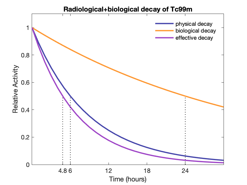
Cumulated activity from initial activity: $\tilde{A} = A \times T_{mean} = A \times T_{1/2} \,/\, \text{ln}(2)$
Aka "Time integrated" (uses the $\text{ln}(2)$ factor)
Remaining fraction: $f = (0.5)^n$ where $n$ is the number of half-lives elapsed
Effective half-life (physical + biological): $T_e = \frac{T_p \cdot T_b}{T_p + T_b} = 1 / (1/T_p + 1/T_b)$
Effective decay constant: $\lambda_e = \lambda_p + \lambda_b$
Transient and Secular equilibrium
Often a radioactive isotope will decay into another radioactive isotope. It is useful to know the relative concentrations of each.
To find the daughter activity, one can use the Bateman equation:
$${\displaystyle A_{d}=A_{P}(0){\frac {\lambda _{d}}{\lambda _{d}-\lambda _{P}}}\times (e^{-\lambda _{P}t}-e^{-\lambda _{d}t})\times BR+A_{d}(0)e^{-\lambda _{d}t},}$$ where $A_P$ and $A_d$ are the parents and daughter activities, $T_P$ and $T_d$ are the corresponding half-lives, and $\lambda_P$ and $\lambda_d$ are the corresponding decay constants. BR is the branching ratio.
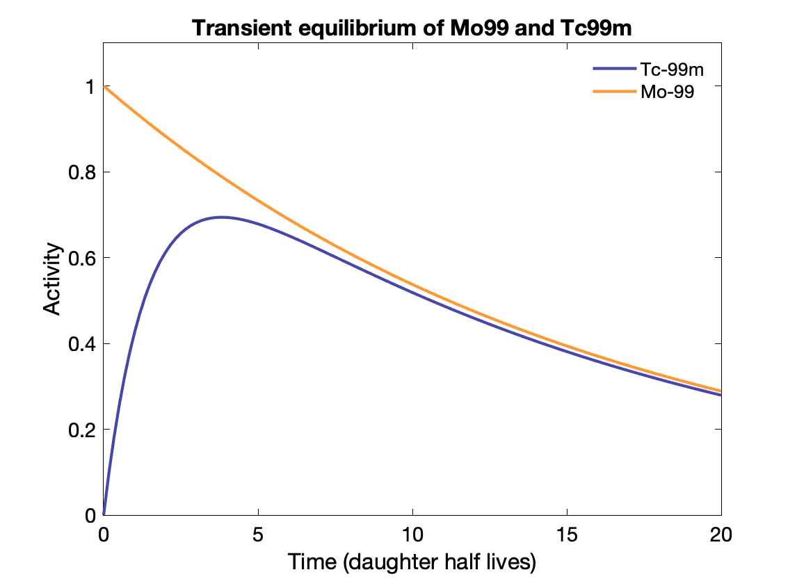
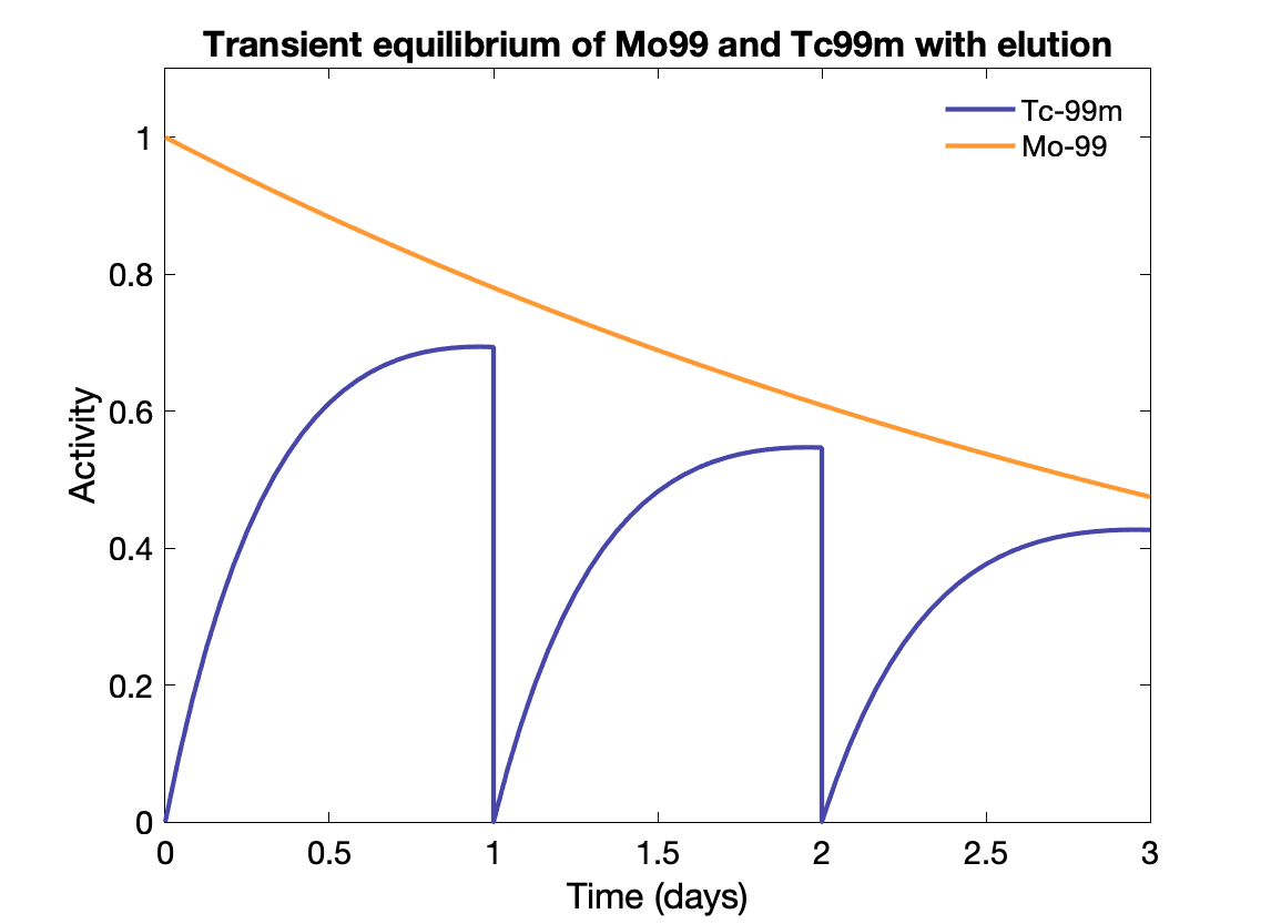
Transient equilibrium: Daughter half-life is shorter, and daughter activity depends on parent activity, but is not the same:
${\displaystyle {\frac {A_{d}}{A_{P}}}={\frac {T_{P}}{T_{P}-T_{d}}}\times BR.}$
Time to transient equilibrium: $t = \frac{\text{ln}(\lambda_d / \lambda_p)}{\lambda_d - \lambda_p}$
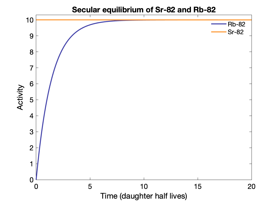
Secular equilibrium happens where the parent half-life is much longer (> 100x) than the daughter's. After 5-6 half-lives, the activity of the parent and daughter are the same if the BR = 1. The daughter activity is produced at the same rate it decays?
E.g., Sr-82 → Rb-82 (25.5d vs 75s).
Note that the Mo-99 only decays to Tc-99m with a branching fraction of 88%, otherwise Tc-99m activity would exceed the parent activity.
Specific activity
Activity per unit mass: $a = \frac{\lambda N_A}{m} = \frac{ln(2) N_A}{T_{1/2} \times m}$ (in Bq/g) where NA is the Avogadro constant.
